Synchronizing Frequency and Phase of Multiple Variable Frequency Power Converters

a power converter and multiple variable frequency technology, applied in the field of power conversion, can solve the problems of difficult synchronization, difficult synchronization, and even more difficult synchronization, if implemented in analog circuitry, and achieves the effect of easy synchronization and synchronization

Active Publication Date: 2009-10-29
SEMICON COMPONENTS IND LLC
View PDF5 Cites 19 Cited by
  • Summary
  • Abstract
  • Description
  • Claims
  • Application Information

AI Technical Summary

Benefits of technology

[0010]Important technical advantages of the present invention are readily appa...

Problems solved by technology

Because most components are made to tolerances (i.e., a range of variation), the natural frequencies of variable frequency power converters (even of the same design) can be different, thus making it difficult to synchronize them.
The three time domain functions are usually implemented by independent time bases—i.e., each has its own timer or oscillator with its respective tolerances—making synchronization even more difficult ...

Method used


Image

  • Synchronizing Frequency and Phase of Multiple Variable Frequency Power Converters
  • Synchronizing Frequency and Phase of Multiple Variable Frequency Power Converters
  • Synchronizing Frequency and Phase of Multiple Variable Frequency Power Converters

Examples


Embodiment Construction

[0019]Embodiments of the present invention and their advantages are best understood by referring to FIGS. 1-7 of the drawings. Like numerals are used for like and corresponding parts of the various drawings.

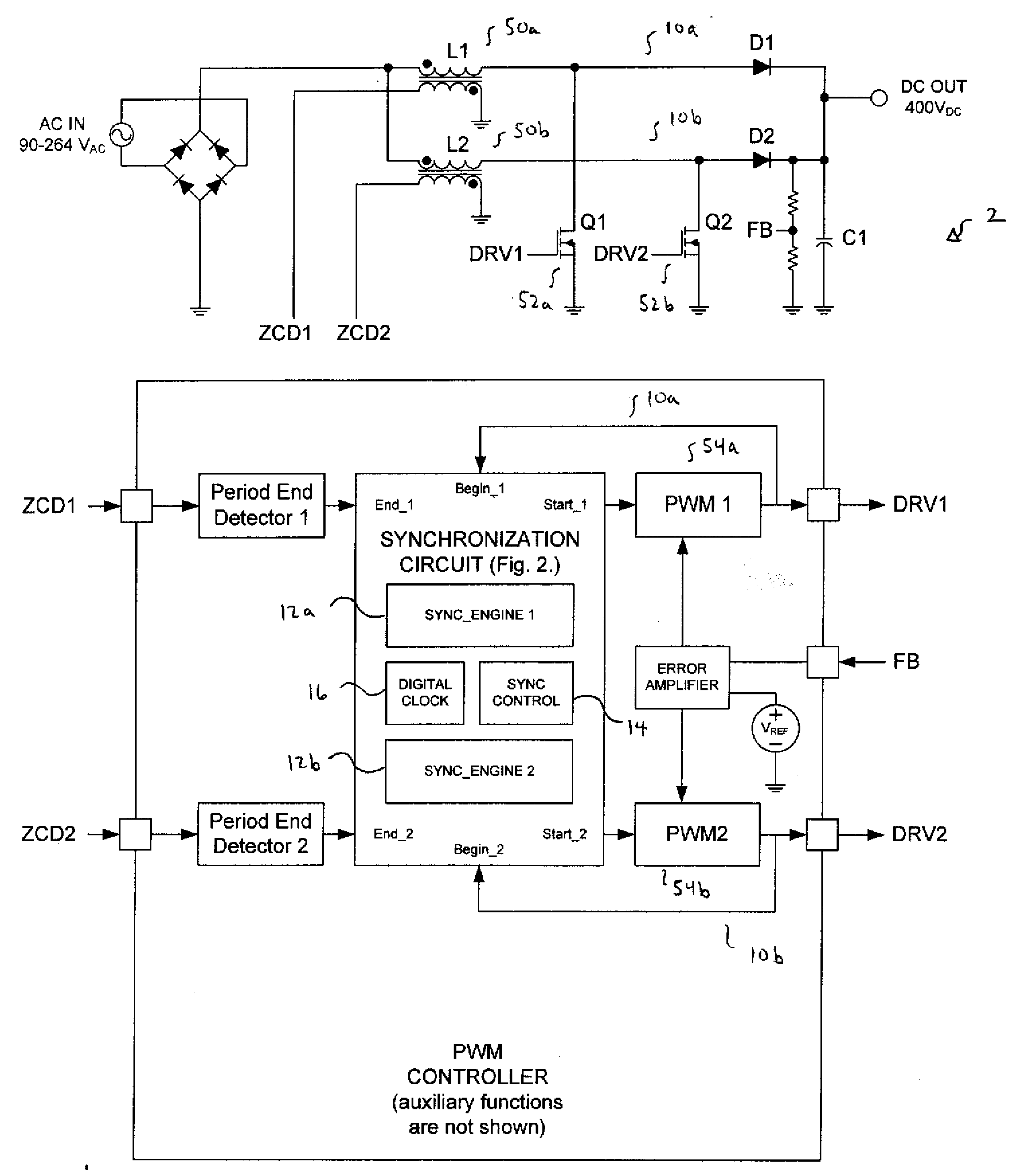
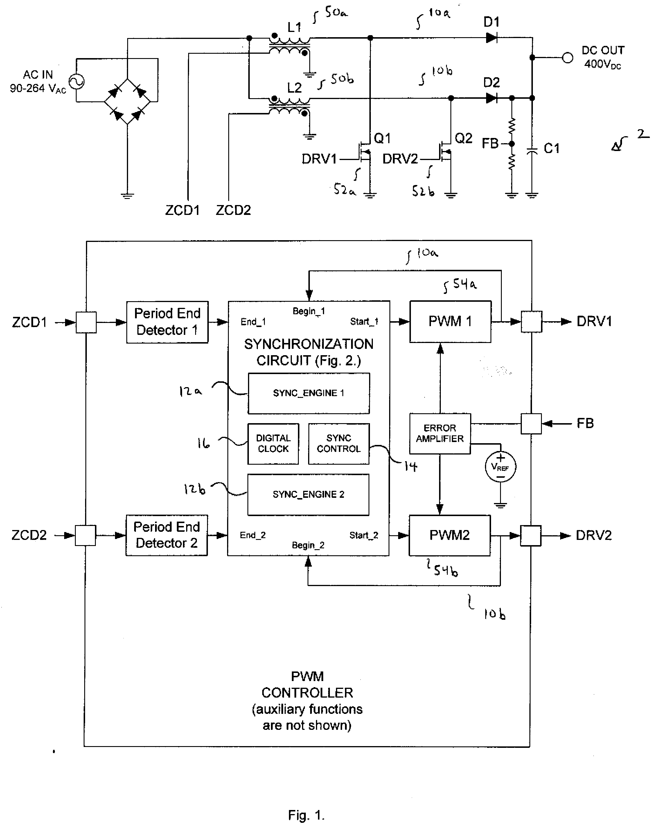
[0020]FIG. 1 illustrates a system 2 having a plurality of variable frequency power converters 10 (separately labeled 10a and 10b) which can be synchronized with circuitry and methods, according to embodiments of the invention.

[0021]As shown, each power converter 10 may include an inductor 50, a switching device 52, and drive circuitry (including a pulse width modulator (PWM) 54). Each power converter 10 can be a switching converter in which the frequency at which the respective switching devices 52 are turned on and off may vary, such as, for example, a boundary conduction mode (BCM) power factor correction (PFC), a quasi-resonant flyback converter, or a resonant converter. As shown, each variable frequency power converter 10 is a BCM PFC converter. In the BCM converters, the ind...


PUM


Abstract

In an embodiment, a power converter system includes a plurality of variable frequency power converters and a plurality of synchronization circuits. Each variable frequency power converter has a switching frequency. Each synchronization circuit is associated with a respective one of the plurality of variable frequency power converters. A control circuit is coupled to and coordinates the plurality of synchronization circuits. The plurality of synchronization circuits and the control circuit are operable to synchronize the switching frequencies of the variable frequency power converters to each other. Each synchronization circuit is operable to: receive a first input signal indicative of the beginning of a switching period for the associated variable frequency power converter; receive a second input signal indicative of the end of the switching period for the associated variable frequency power converter; generate a first output signal for directing a pulse width modulation of the associated variable frequency power converter; and generate a second output signal for coordinating a phase relationship with another variable frequency power converter in the system.

Description

BACKGROUND[0001]1. Field of Invention[0002]The present invention relates to power conversion, and more particularly, to synchronizing frequency and phase of multiple variable frequency power converters.[0003]2. Description of Related Art[0004]Power converters are essential for many modern electronic devices. Among other capabilities, a power converter can adjust voltage level downward (buck converter and its derivatives) or adjust voltage level upward (boost converter and its derivatives). A power converter may also convert from alternating current (AC) power to direct current (DC) power, or vice versa. A power converter may also function to provide an output at a regulated level (e.g., 5.0V). Power converters are typically implemented using one or more switching devices, such as transistors, which are turned on and off to deliver power to the output of the converter. Control circuitry is provided to regulate the turning on and off of the switching devices, and thus, these converter...

Claims


Application Information

Patent Timeline
IPC IPC(8): H03L7/00
CPCH02M2003/1586H02M3/1584H02M3/1586
Inventor BRIDGE, CHRISTOPHER D.BALOGH, LASZLO
Owner SEMICON COMPONENTS IND LLC
Why Eureka
Try Eureka