Dual supply inverter for voltage controlled ring oscillator

a voltage control and logic circuit technology, applied in the direction of logic circuit pulse generation, pulse generator, pulse technique, etc., can solve the problems of significant change in oscillation frequency, vdd, and very sensitive oscillation frequency of oscillator

Inactive Publication Date: 2009-10-29
REALTEK SEMICON CORP
View PDF8 Cites 12 Cited by
  • Summary
  • Abstract
  • Description
  • Claims
  • Application Information

AI Technical Summary

Problems solved by technology

One drawback to the ring oscillator 100 shown in FIG. 1A is that the oscillator frequency is very sensitive to the level of the control voltage (i.e., VDD).
A slight change in the level of the control voltage usually leads to a significant change in the oscillation frequency.
Such sensitivity is usually not desirable, since the ring oscillator would be highly susceptible to noise in the control voltage.

Method used


Image

  • Dual supply inverter for voltage controlled ring oscillator
  • Dual supply inverter for voltage controlled ring oscillator
  • Dual supply inverter for voltage controlled ring oscillator

Examples


Embodiment Construction

[0030]The present invention relates to a method and an apparatus to reduce sensitivity of a circuit delay in response to a variable voltage. While the specification describes several example embodiments of the invention, it should be understood that the invention can be implemented in many way and is not limited to the particular examples described below or to the particular manner in which any features of such examples are implemented.

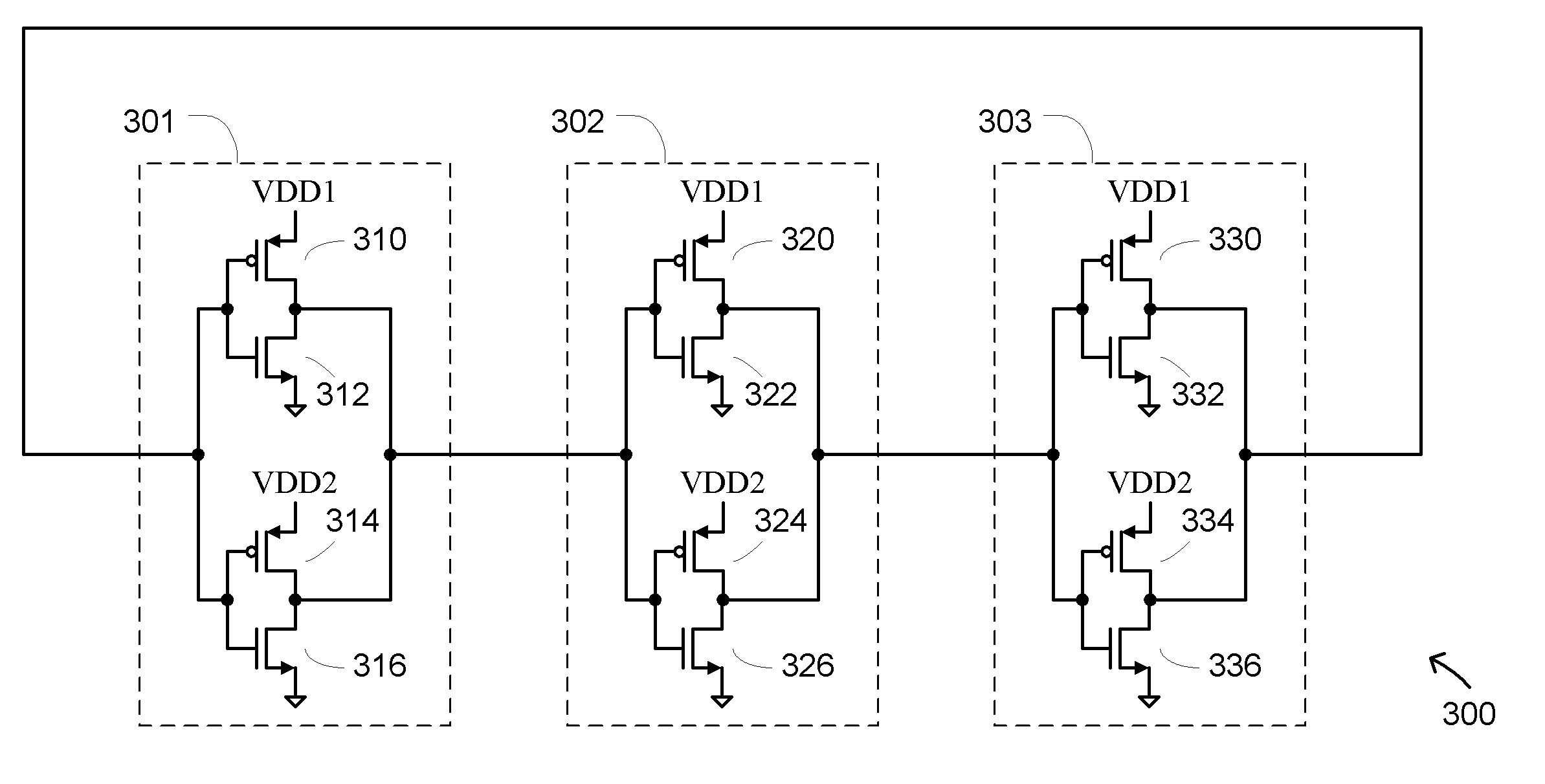
[0031]FIG. 2 is a block diagram of a dual supply inverter 200 in accordance with one embodiment of the present invention. The dual supply inverter 200 comprises a first inverter logic circuit 201 and a second inverter logic circuit 202 configured in a parallel topology. That is, the first inverter logic circuit 201 is coupled in parallel with the second inverter logic circuit 202 such that they share a common input terminal (input) and a common output terminal (output). The first inverter logic circuit 201 receives power from a first supply voltage (V...


PUM


Abstract

A voltage controlled ring oscillator reduces sensitivity of an oscillation frequency to a control voltage by using a dual supply inverter logic circuit. The dual supply inverter logic circuit includes two inverter circuits coupled in parallel between an input terminal and an output terminal. The first inverter circuit is powered by a variable supply voltage while the second inverter circuit is powered by a substantially fixed supply voltage. The variable supply voltage serves as the control voltage for the voltage controlled ring oscillator and sets the oscillation frequency. The sensitivity of the oscillation frequency to changes in the variable supply voltage is reduced due to the parallel connection of the second inverter circuit powered by a different supply voltage.

Description

[0001]The present application claims priority benefits under 35 U.S.C. §119(e) from U.S. Provisional Application No. 61 / 048,211, filed on Apr. 27, 2008, entitled “Dual Supply Inverter for Voltage Controlled Ring Oscillator,” which is hereby incorporated herein in its entirety by reference.BACKGROUND OF THE INVENTION[0002]1. Field of the Invention[0003]The present invention relates to a dual supply inverter logic circuit and in particular to a method and apparatus for using the dual supply inverter logic circuit in a voltage controlled oscillator application.[0004]2. Description of the Related Art[0005]A ring oscillator is widely used to implement a voltage controlled oscillator (VCO). FIG. 1A depicts a 3-stage ring oscillator 100 comprising three inverter stages 101-103 configured in a ring topology. Each inverter stage is powered by a common power supply voltage VDD. Each inverter stage introduces a 180 degrees phase shift, due to its inversion function, plus an additional phase sh...

Claims


Application Information

Patent Timeline
Patent Type & Authority Applications(United States)
IPC IPC(8): H03K3/03
CPCH03K3/0315
Inventor LIN, CHIA-LIANG
Owner REALTEK SEMICON CORP
Why Eureka
Try Eureka