

Superconducting magnet
a superconducting magnet and superconducting coil technology, applied in the direction of superconducting magnets/coils, magnetic bodies, magnetic materials, etc., can solve the problems of high critical temperature of superconductors
- Summary
- Abstract
- Description
- Claims
- Application Information
AI Technical Summary
Benefits of technology
Problems solved by technology
Method used
Image

Examples
first embodiment
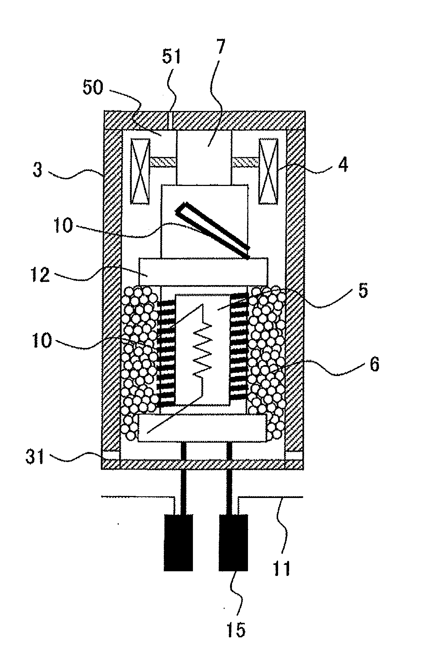
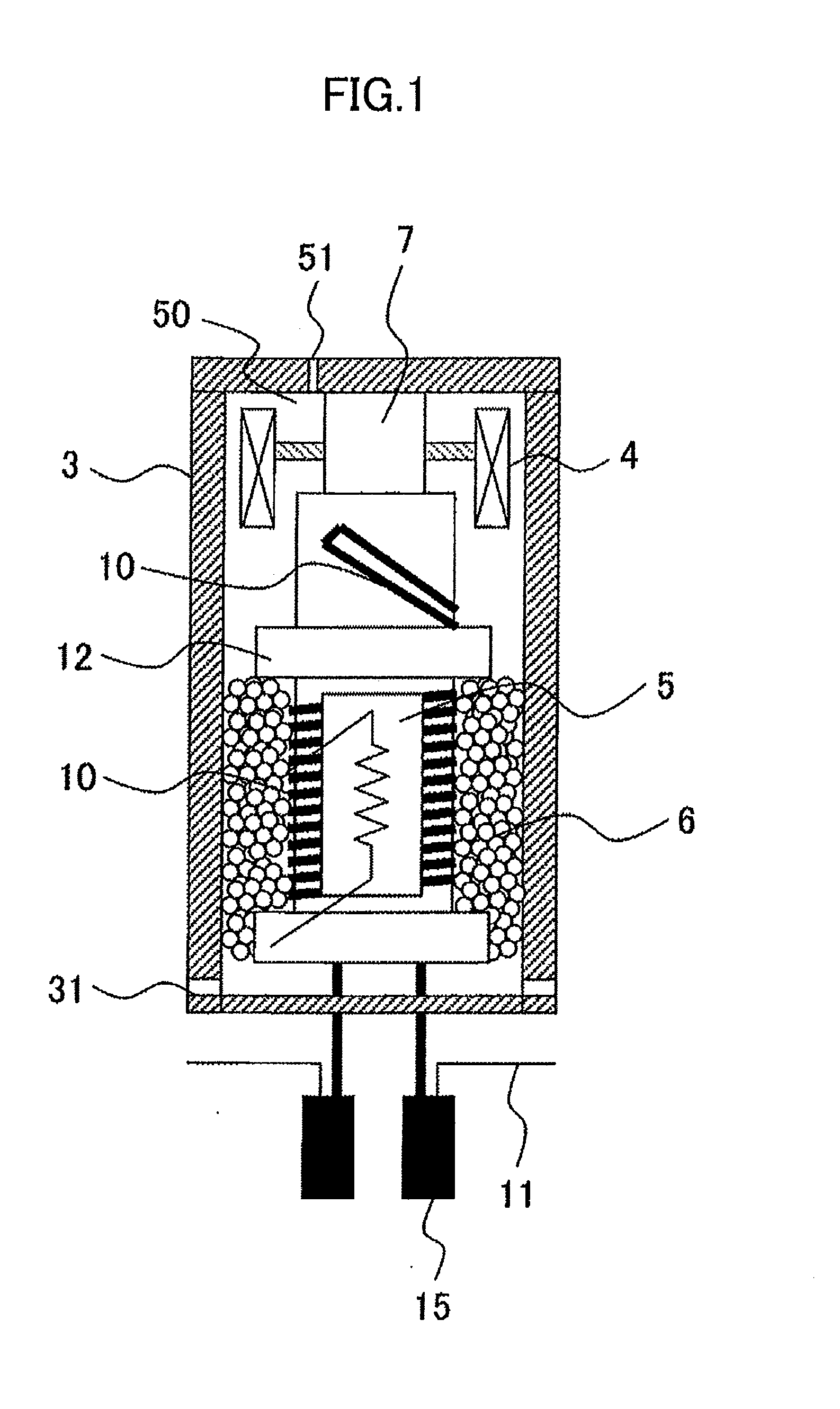
[0051]FIG. 1 is a cross sectional view showing a configuration of a persistent current switch according to the first embodiment of the present invention.
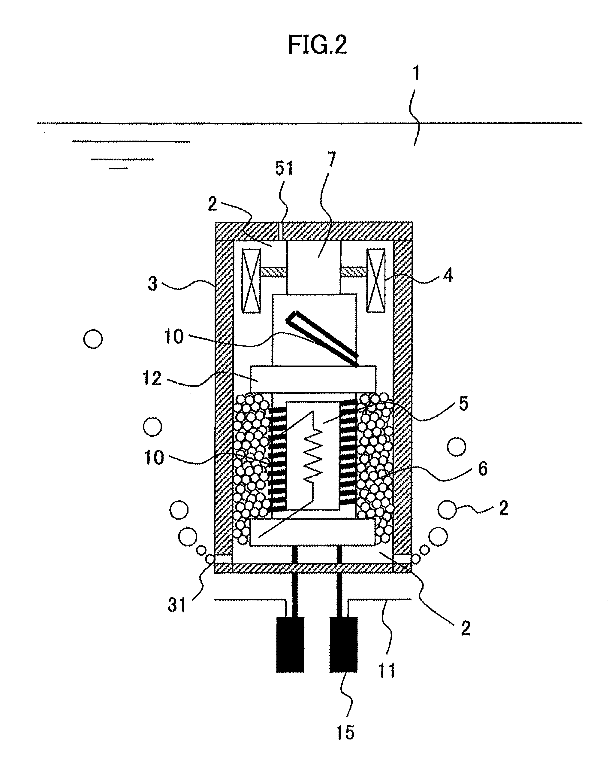
[0052]In FIG. 1, a vessel 3 houses therein the winding part 20 (not shown). A side surface of an inner wall of the vessel 3 is spaced apart from a side face of the winding part 20. In this embodiment, an inner diameter of the vessel 3 is 58 mm, and an outer diameter of the winding part 20 is 50 mm. The vessel 3 has a through hole 31 below a lower surface of the winding part 20. A size and the number of the through hole 31 is adjusted according to a liquid level of liquid helium and a position to which the persistent current switch is attached.
[0053]The size of the through hole 31 is required to be large enough such that a pressure inside the vessel 3 in a state of being filled with helium gas 2 (see FIG. 2) is higher than a pressure exerted by the liquid level. For example, if the size of the through hole 31 is too large or the thro...
second embodiment
[0071]FIG. 4 is a cross sectional view showing a configuration of a persistent current switch according to a second embodiment of the present invention.
[0072]FIG. 4 assumes that the persistent current switch is horizontally disposed due to, for example, a height restriction. The support member 7 fixes the winding part 20 in which the superconductive wire is wound around, to the inner wall of the vessel 3 disposed around the winding part 20. In FIG. 4, the winding part 20 is fixed from the side surface of the vessel 3. However, the winding part 20 may be fixed from the top surface or a bottom surface of the vessel 3.
[0073]The vessel 3 is also horizontally arranged. The vessel 3 has the through hole 31 below the lowermost surface of the winding part 20 disposed in the vessel 3. The helium gas storage part 50 is disposed in the upper portion of the vessel 3. The cryogen-heating heater 4 is disposed in the helium gas storage part 50. If the extracting part 21 (see FIG. 7) into which the...
third embodiment
[0075]FIG. 5 is a cross sectional view showing a configuration of a persistent current switch according to a third embodiment of the present invention.
[0076]FIG. 5 assumes that the persistent current switch described in the first embodiment is disposed upside down due to, for example, a restriction in placing the extracting part 21. The support member 7 fixes the winding part 20 in which superconductive wire is wound around, to the inner wall of the vessel 3 disposed around the winding part 20. In FIG. 5, the winding part 20 is fixed from the bottom surface of the vessel 3. However, the winding part 20 may be fixed from the top surface or side surface of the vessel 3.
[0077]The vessel 3 has the through hole 31 below the lowermost surface of the winding part 20 fixed into the vessel 3. The helium gas storage part 50 is disposed at the upper portion of the vessel 3. The cryogen-heating heater 4 is disposed in the helium gas storage part 50. Since the extracting part 21 penetrates the v...
PUM
 Abstract
Description
Claims
Application Information