Optical Interferometric Sensor

Inactive Publication Date: 2009-10-29
SYMPHONY ACOUSTICS
View PDF2 Cites 26 Cited by
  • Summary
  • Abstract
  • Description
  • Claims
  • Application Information

AI Technical Summary

Benefits of technology

[0015]In some embodiments, an optically resonant cavity is interrogated by an array of sources, each of which provides light having a first wavelength to the cavity. The light from each source that is reflected from the cavity is detected by one of a first array of photodetectors. The collective outputs of all these photodetectors provide an average reflected signal from the optically resonant cavity. In some embodiments, the light from each source that is transmitted by the cavity is detected by one of a second array of photodetectors. The collective outputs of all of these photodetectors provide an average transmitted signal from the optically resonant cavity. By averaging the reflected and/or transmitted signals received from the optically resonant cavity, the effect of noise associated with any one source is mitigated.
[0016]In some embodiments, each source in the source array provides light having a different wavelength. As a result, at least one of the source/detector pairs/trios can operate at a point of maximum sensitivity to chan

Problems solved by technology

In some embodiments, only some of the sources in the source array are operat

Method used


Image

  • Optical Interferometric Sensor
  • Optical Interferometric Sensor
  • Optical Interferometric Sensor

Examples


Embodiment Construction

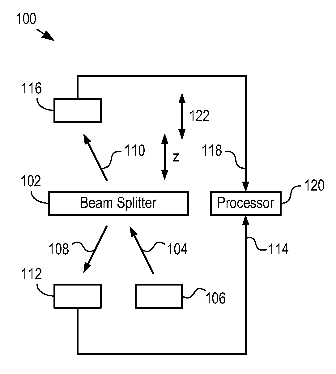
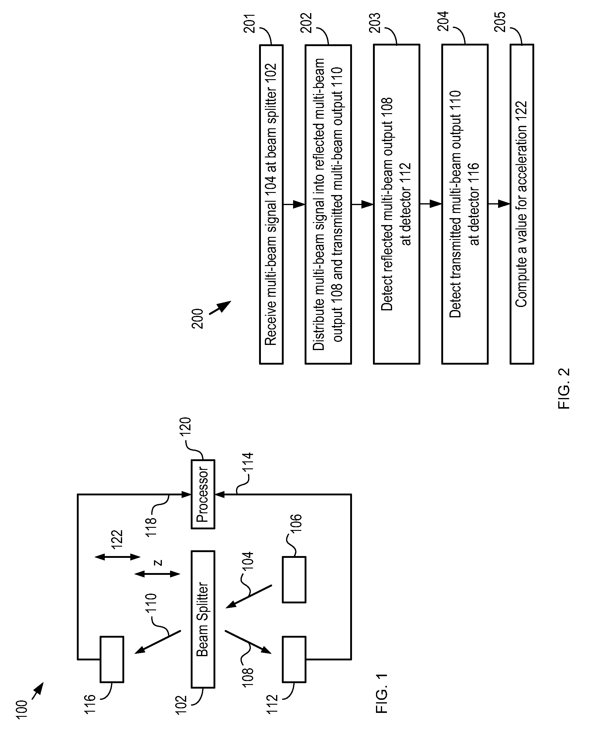
[0033]FIG. 1 depicts a schematic diagram of details of an environment stimulus sensor in accordance with an illustrative embodiment of the present invention. Sensor 100 comprises beam splitter 102, source 106, detector 112, detector 116, and processor 120. Environmental stimulus sensor 100 provides an output signal based on acceleration 122, which applies to sensor 100 along the z-direction as shown. Although the illustrative embodiment is an acceleration sensor, it will be clear to one skilled in the art, after reading this specification, how to specify, make, and use alternative embodiments of the present invention that sense other environmental stimuli, such as vibration, acoustic energy, shock, and pressure.

[0034]FIG. 2 depicts operations of a method for sensing an environmental stimulus in accordance with the illustrative embodiment. FIG. 2 is described with continuing reference to FIG. 1. Method 200 begins with operation 201, wherein beam splitter 102 receives multi-beam signa...


PUM


Abstract

Embodiments of environmental stimulus sensors comprising multiple sources and detectors for interrogating one or more optically resonant cavities that are responsive to one or more environmental stimuli are disclosed. Such sensors have, among other advantages, improved immunity to source and/or detector noise.

Description

CROSS REFERENCE TO RELATED APPLICATIONS[0001]This case claims priority to: U.S. Provisional Patent Application Ser. No. 61 / 047,936, filed Apr. 25, 2008 (Attorney Docket: 123-100US), which is incorporated by reference.[0002]In addition, the underlying concepts, but not necessarily the language, of the following cases are incorporated by reference:[0003](1) U.S. patent application Ser. No. 12 / 122,342, filed May 16, 2008 (Attorney Docket: 123-012US); and[0004](2) U.S. patent application Ser. No. 11 / 460,626, filed Jul. 28, 2006 (Attorney Docket: 123-040US); and[0005](3) U.S. patent application Ser. No. 11 / 927,234, filed Oct. 29, 2007 (Attorney Docket: 123-060US).[0006]If there are any contradictions or inconsistencies in language between this application and one or more of the cases that have been incorporated by reference that might affect the interpretation of the claims in this case, the claims in this case should be interpreted to be consistent with the language in this case.FIELD O...

Claims


Application Information

Patent Timeline
IPC IPC(8): G01B11/02
CPCG01P15/093G01H9/00
Inventor CARR, DUSTIN WADEBOGART, GREGORY ROBERT
Owner SYMPHONY ACOUSTICS
Why Eureka
Try Eureka