Oblique Tourbillon

Inactive Publication Date: 2009-10-29
WATCH U LICENSE
View PDF0 Cites 14 Cited by
  • Summary
  • Abstract
  • Description
  • Claims
  • Application Information

AI Technical Summary

Benefits of technology

[0006]Consistent with embodiments of the present invention, a tourbillon is provided with an improved, positionally-optimised accuracy. Also, consistent with embodi

Problems solved by technology

However, a commercial implementation of Walter Prendel's flying tourbillon is not practical, due to its complicated structure.
However, the manufacture of the gear wheel requires a relatively large outlay

Method used


Image

  • Oblique Tourbillon
  • Oblique Tourbillon

Examples


Embodiment Construction

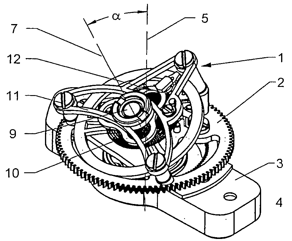
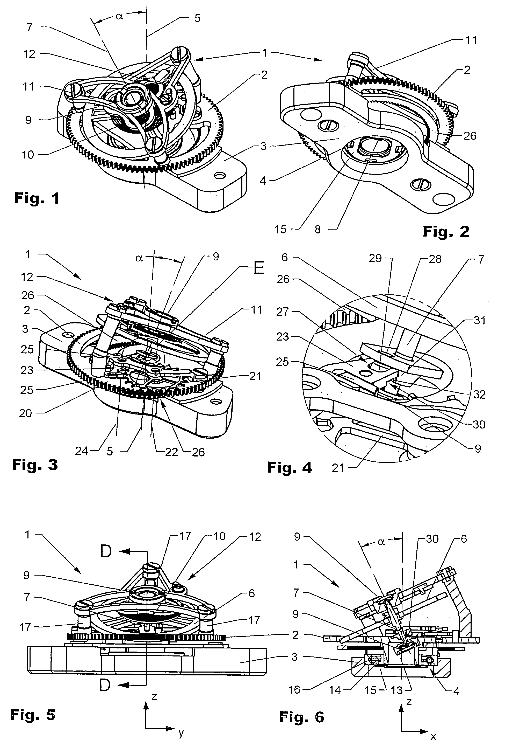
[0019]FIGS. 1 to 6 all show by way of example a flying tourbillon, or a tourbillon module 1. Corresponding parts therefore have the same reference number.

[0020]As is particularly clear from FIGS. 1-3 and 5, the tourbillon 1 substantially includes a tourbillon platform 2 that is opposite a tourbillon base 3 and rotatably mounted about a platform axis 5 by means of a ball bearing (main bearing) 4. A balance-wheel 6 that is rotatably mounted about a balance-staff 7 is arranged on the tourbillon platform 2. The balance-staff 7 is held by an upper and by a lower balance-wheel bearing 8, 9 that is fixed to the platform 2. A balance-spring 10 is operatively linked on one end to the balance-wheel 6 and in the area of the other end to a balance-cock 11, or may be operatively linked to an adjusting mechanism 12. The balance-cock 11 is supported by supports 17 opposite the platform 2. The balance-staff 7 is arranged at an angle of inclination ∝ with respect to the platform axis 5. In the exemp...


PUM


Abstract

A tourbillon is provided that includes a platform rotatable about a platform axis. In one implementation, the platform carries an escapement including an escape-wheel and pallets, wherein the escape-wheel is rotatable about an escape-wheel staff, the pallets are rotatable about a pallet-staff, and the escape-wheel staff and the pallet-staff are disposed so as to be essentially parallel to the platform axis. The platform also carries a balance-wheel rotatable about a balance-staff, wherein the balance-staff is arranged at an angle of inclination ∝ with respect to the platform axis.

Description

[0001]This application is a national stage filing under 35 U.S.C. § 371 of International Application No. PCT / CH2006 / 000513, filed Sep. 22, 2006, which published in the German language, and which claims priority to Swiss (CH) Patent Application No. 1562 / 05, filed Sep. 23, 2005.TECHNICAL FIELD[0002]The present disclosure relates to the field of horology and, more specifically to embodiments of tourbillons or tourbillon modules.BACKGROUND INFORMATION[0003]Conventional watch movements include tourbillons in which the rotation axis of the balance wheel is arranged either parallel or perpendicular to the rotation axis of the tourbillon platform. In addition, tourbillons are known in which the rotation axis of the balance wheel is arranged at an angle to the rotation axis of the platform. The purpose of these devices is to prevent the positional inaccuracy of the balance wheel caused by overlapping motions. A very complicated example of a tourbillon is Walter Prendel's flying tourbillon cr...

Claims


Application Information

Patent Timeline
IPC IPC(8): G04B15/00
CPCG04B17/285
Inventor SALATHE, WILLY
Owner WATCH U LICENSE
Why Eureka
Try Eureka