

Data transmission bridge device and control chip thereof for transmitting data
- Summary
- Abstract
- Description
- Claims
- Application Information
AI Technical Summary
Benefits of technology
Problems solved by technology
Method used
Image

Examples
Embodiment Construction
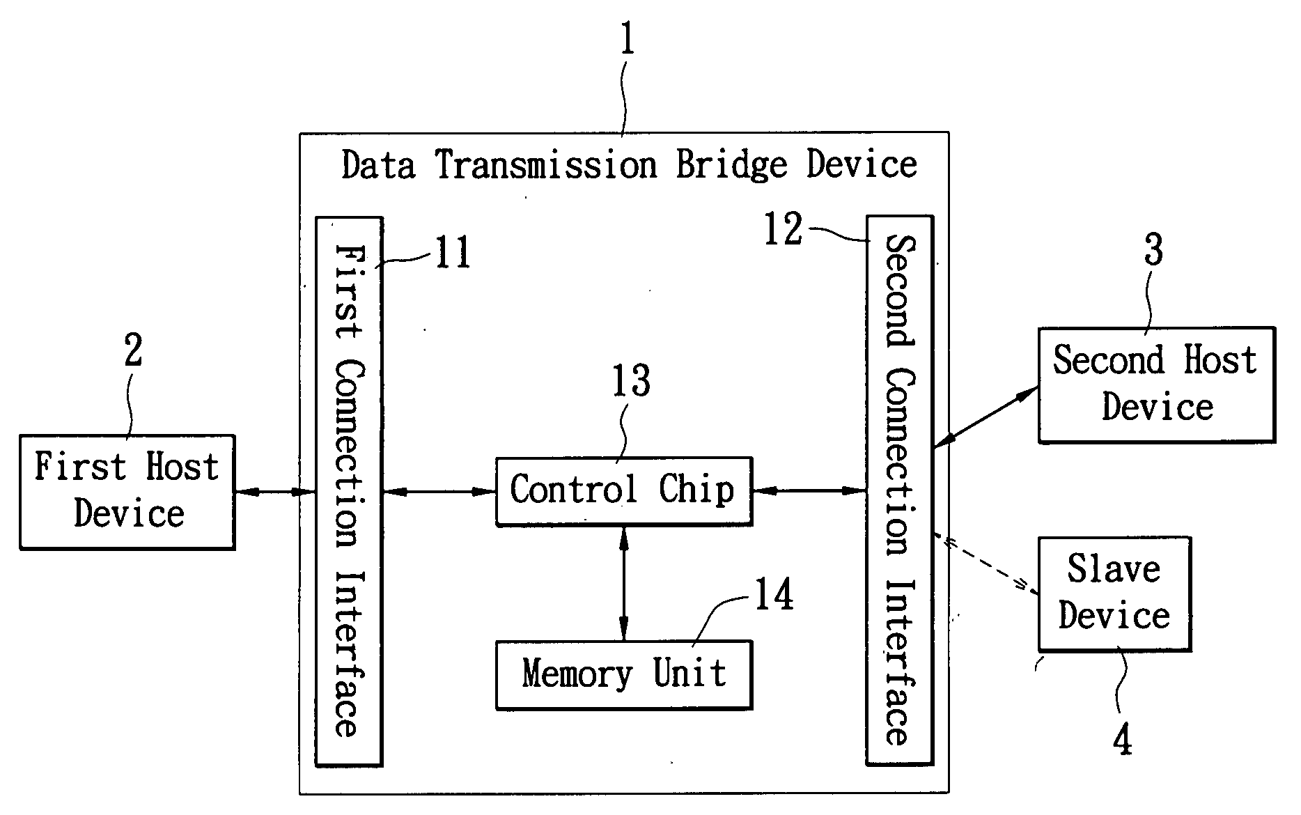
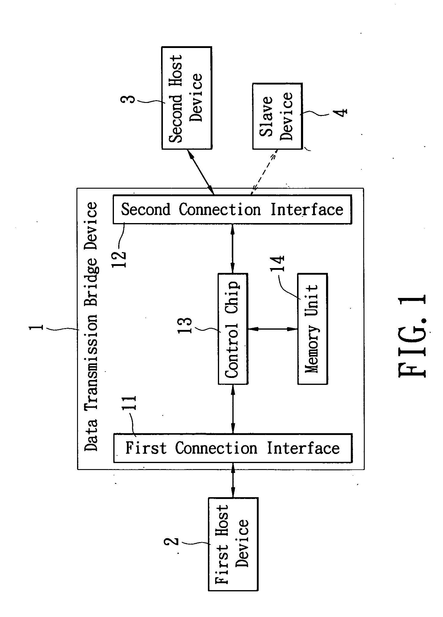
[0021]The present Invention designed a data transmission bridge device for transmitting data between two devices (host-host or host-slave) through simple hardware structure, the main feature is the provision of two different transmission paths, so that by automatically detecting the type of device connected (host or slave) the present invention can switch to the proper transmission path, thus not only can host-slave operation between the host device and the slave device be supported, but direct bridging between two host device for data transfer is also possible. Further more the present invention adheres to USB specification by design, so that “plug and play” works properly. Thus the goal of allowing users to conveniently bridge between a host device and any other device (host or slave) for data transfer is achieved.
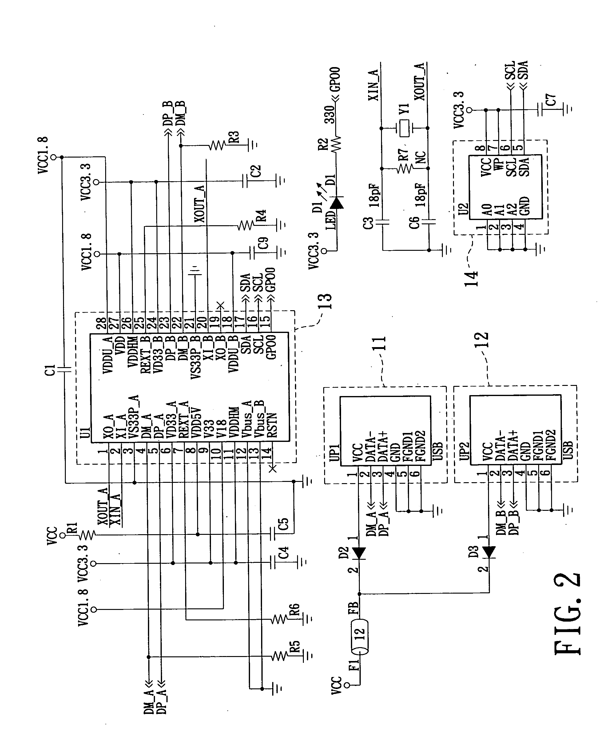
[0022]Please reference FIG. 1 and FIG. 2 in conjunction, which respectively shows an embodiment of a schematic circuit diagram for a data transmission bridge device and ...
PUM
 Abstract
Description
Claims
Application Information