Gateway for Data Transfer Between Serial Buses

Active Publication Date: 2009-10-29
ROBERT BOSCH GMBH
View PDF16 Cites 14 Cited by
  • Summary
  • Abstract
  • Description
  • Claims
  • Application Information

AI Technical Summary

Benefits of technology

[0015]It is therefore an object of the exemplary embodiments and/or exemplary methods of the present invention to create a ga

Problems solved by technology

This CPU interface is heavily loaded by this data exchange in addition to the messages to be transferred to the user itself; in combination with the transfer structure resulting therefrom, this results in a relatively low data transfer speed.
A disadvantage with the conventional procedure for transferring data with the conventional gateway according to the existing art depicted in FIG. 1 is that a

Method used


Image

  • Gateway for Data Transfer Between Serial Buses
  • Gateway for Data Transfer Between Serial Buses
  • Gateway for Data Transfer Between Serial Buses

Examples


Example

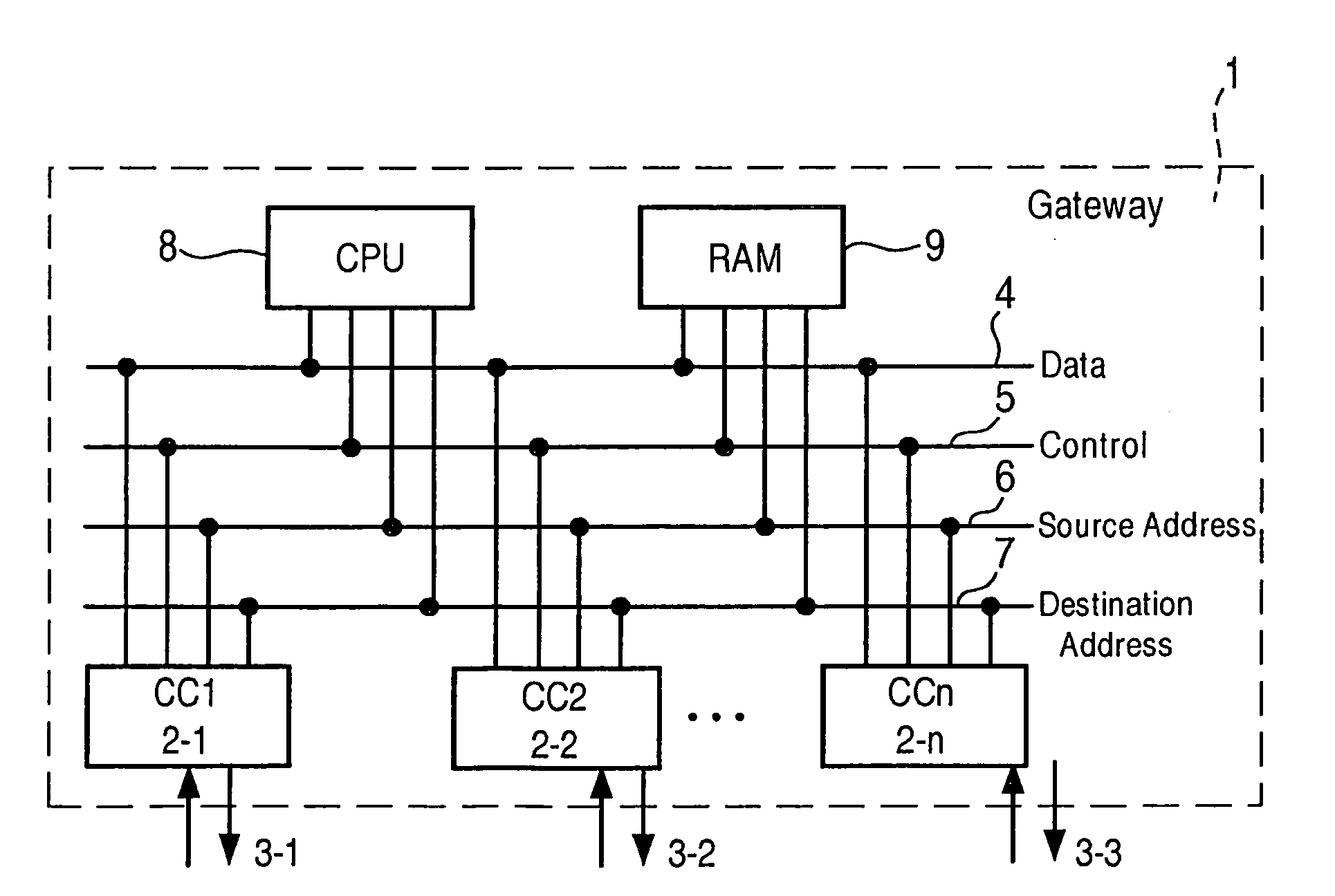
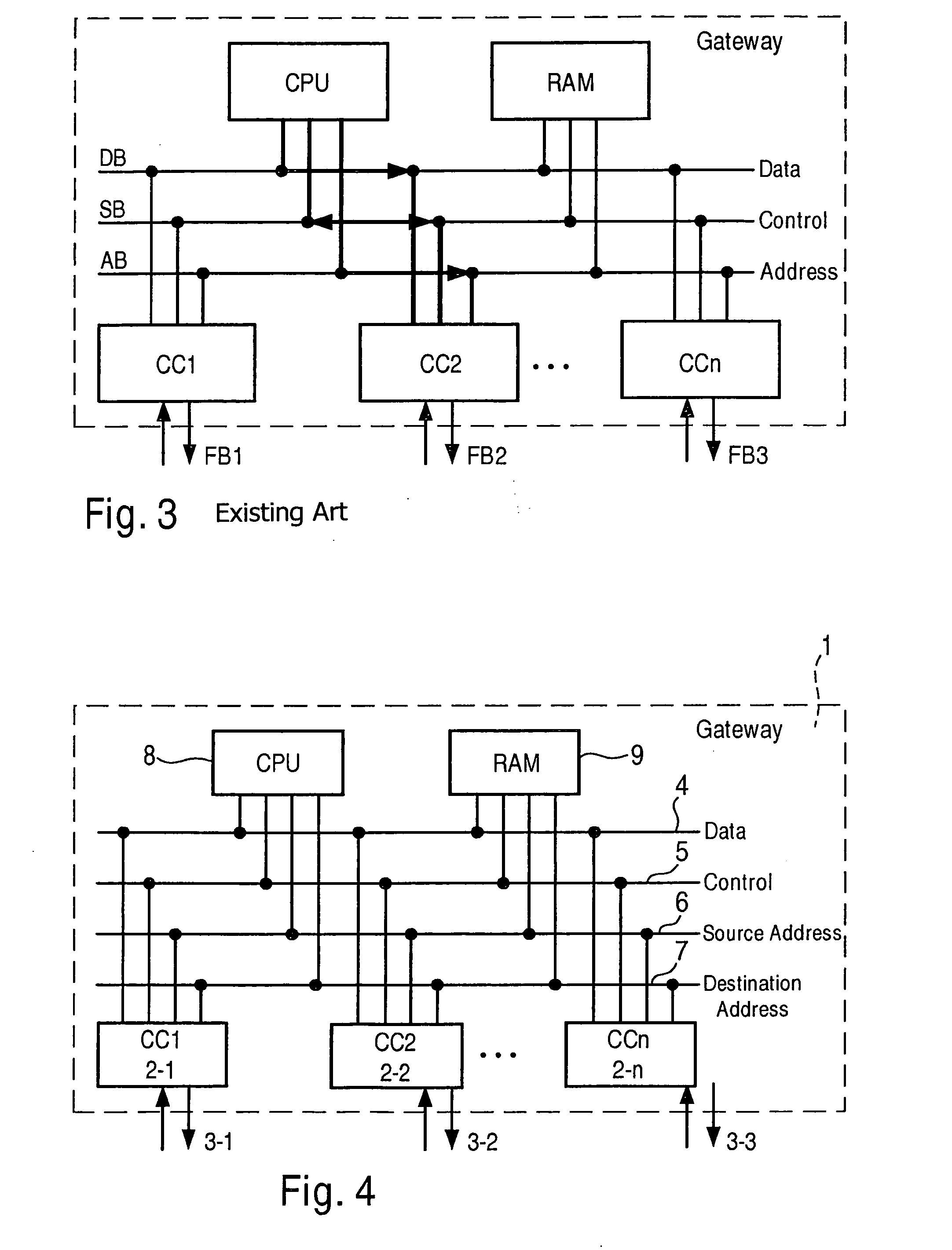
[0034]FIG. 4 shows a specific embodiment of gateway 1 according to the present invention for data transfer between different serial buses. Gateway 1 has multiple communication modules 2 that are each provided for connection of one serial bus 3. Serial buses 3 can be, for example, field buses. Alternatively, the serial buses can also be Ethernet buses. Possible serial field buses are a CAN bus, a FlexRay bus, a MOST bus, or a LIN bus. Data are transferred via serial buses 3-i in packet fashion, the transferred data packets encompassing administrative or header data, and useful or payload data.

[0035]The gateway according to the exemplary embodiments and / or exemplary methods of the present invention has an internal system bus that encompasses an internal data bus 4, an internal control bus 5, a source address bus 6, and a destination address bus 7. At least one data processing unit 8, in the form of a processor and a data memory 9, is connected to the system bus. CPU 8 constitutes the ...


PUM


Abstract

A gateway for data transfer between serial buses, including multiple communication modules that are each provided for connection of one serial bus, and that carry out a conversion between data packets and data words, a bus master that, via an internal control bus, controls a word-based transfer of data via an internal data bus between two communication modules, the bus master applying a source address via a source address bus to an internally transmitting first communication module, and a destination address via a separate destination address bus to an internally receiving second communication module, data received in data packets by the first communication module via a first serial bus connected thereto being transferred from the first communication module directly without buffering, in word-based fashion in one or more data words, via the internal data bus to the second communication module, which delivers these transferred data, in data packets, via a second serial bus connected to the second communication module.

Description

FIELD OF THE INVENTION[0001]The present invention relates to a gateway for data transfer between serial buses, in particular between field buses.BACKGROUND INFORMATION[0002]The networking of control units, sensor apparatus, and actuators with the aid of a network or communication system made up of a communication connection, in particular a bus, and corresponding communication modules, has drastically increased in recent years in the design of modern motor vehicles or also in mechanical engineering, especially in the machine-tool sector, and in automation. Synergistic effects resulting from the distribution of functions to multiple users, in particular control units, can be achieved in this context. The term used is “distributed systems.” Such distributed systems or networks are thus made up of the users and the bus system or multiple bus systems connecting those users. Communication between different stations or users is thus taking place more and more via a communication system, b...

Claims


Application Information

Patent Timeline
IPC IPC(8): H04L12/56
CPCG06F13/4027H04L12/46H04L2012/40241H04L12/66H04L2012/40215H04L12/4625
Inventor IHLE, MARKUSLORENZ, TOBIASTAUBE, JAN
Owner ROBERT BOSCH GMBH
Why Eureka
Try Eureka