Variable displacement type compressor with displacement control mechanism

a variable displacement type and compressor technology, applied in the direction of machines/engines, multi-cylinder pumps, positive displacement liquid engines, etc., can solve the problems of spool movement, excessive pressure in the pressure control chamber, and long time before the displacement of the compressor is increased to the desired level

Active Publication Date: 2009-10-29
TOYOTA IND CORP
View PDF8 Cites 25 Cited by
  • Summary
  • Abstract
  • Description
  • Claims
  • Application Information

AI Technical Summary

Benefits of technology

[0012]A variable displacement type compressor in which a discharge-pressure region, a suction-pressure region and a pressure control chamber are defined, has a tiltable swash plate and a piston reciprocated by the swash plate in the pressure control chamber. The inclination angle of the swash plate and the piston stroke are changed by adjustment of pressure in the pressure control chamber thereby to control the displacement of the compressor The compressor further comprises a supply passage for supplying refrigerant gas from the discharge-pressure region to the pressure control chamber, a release passage for releasing the refrigerant gas from the pressure control chamber to the suction-pressure region, a first control valve for adjusting a cross-sectional area of the supply passage from the discharge-pressure region to the pressure control chamber and a second control valve for adjusting cross-sectional area of the release passage. The second control valve includes a valve body for opening and closing the release passage whose cross-sectional area is set minimum when the valve body is located at the closed position and a valve spring for urging the valve body in a direction to open the release passage. When the second control valve is closed, pressure in the supply passage downstream the first control valve acts on the valve body in a direction to close the release passage and pressure in the suction-pressure region acts on the valve body in a direction to open the release passage.

Problems solved by technology

As a result, the liquefied refrigerant is vaporized in the pressure control chamber and the pressure in the pressure control chamber is increased excessively.
Therefore, it takes a long time before the displacement of the compressor is increased to a desired level after the compressor is started
If the spring force of the spool spring is too small, however, the spool movement may be hampered by any foreign matters present between the peripheral surface of the spool and its accommodation chamber This prevents the liquefied refrigerant in the pressure control chamber from being rapidly released when the compressor is started.
If the cross-sectional area of the bleed hole is made too large, an excessive amount of refrigerant gas is released from the pressure control chamber to the suction chamber, with the result that the operating efficiency is deteriorated.

Method used


Image

  • Variable displacement type compressor with displacement control mechanism
  • Variable displacement type compressor with displacement control mechanism
  • Variable displacement type compressor with displacement control mechanism

Examples


Embodiment Construction

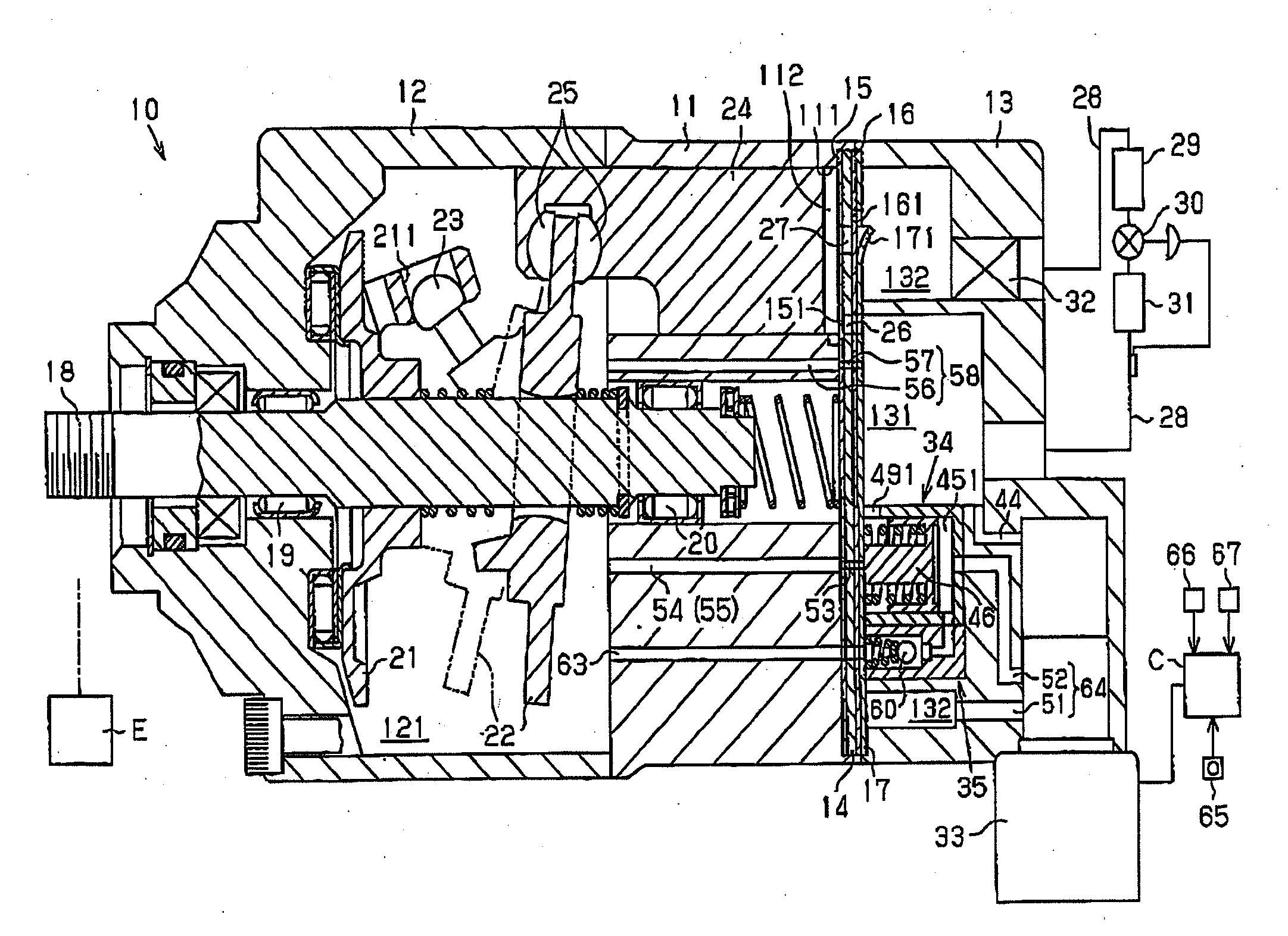
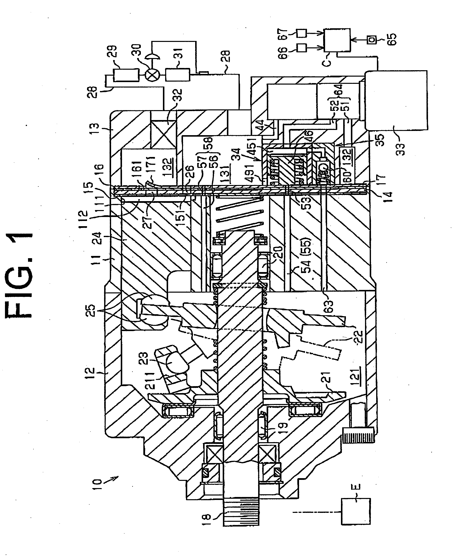
[0019]The first preferred embodiment of a clutchless variable displacement type compressor according to the present invention will now be described with reference to FIGS. 1 through 3. The compressor is generally designated by numeral 10. The left side and the right side of the compressor 10 as viewed in FIG. 1 correspond to the front side and the rear side thereof. As shown in FIG. 1, the compressor 10 includes a cylinder block 11 and a front housing 12 connected to the front end of the cylinder block 11. A rear housing 13 is connected to the rear end of the cylinder block 11 through a valve plate 14, valve forming plates 15, 16 and a retainer forming plate 17. The cylinder block 11, the front housing 12 and the rear housing 13 cooperate to form the entire housing of the variable displacement type compressor 10.

[0020]The front housing 12 and the cylinder block 11 define therebetween a pressure control chamber 121. A rotary shaft 18 is rotatably supported by the front housing 12 and...


PUM


Abstract

A variable displacement type compressor in which a discharge-pressure region, a suction-pressure region and a pressure control chamber are defined, has a tiltable swash plate and a piston reciprocated by the swash plate in the pressure control chamber. The inclination angle of the swash plate and the piston stroke are changed by adjustment of pressure in the pressure control chamber thereby to control the displacement of the compressor. The compressor further comprises a supply passage for supplying refrigerant gas from the discharge-pressure region to the pressure control chamber, a release passage for releasing the refrigerant gas from the pressure control chamber to the suction-pressure region, a first control valve for adjusting a cross-sectional area of the supply passage from the discharge-pressure region to the pressure control chamber and a second control valve for adjusting cross-sectional area of the release passage. The second control valve includes a valve body for opening and closing the release passage whose cross-sectional area is set minimum when the valve body is located at the closed position and a valve spring for urging the valve body in a direction to open the release passage. When the second control valve is closed, pressure in the supply passage downstream the first control valve acts on the valve body in a direction to close the release passage and pressure in the suction-pressure region acts on the valve body in a direction to open the release passage.

Description

BACKGROUND OF THE INVENTION[0001]The present invention relates to a displacement control mechanism for a variable displacement type compressor which adjusts the pressure in a pressure control chamber by supplying refrigerant gas in a discharge-pressure region into the pressure control chamber and releasing the refrigerant gas in the pressure control chamber to a suction-pressure region, thereby controlling the displacement of the compressor.[0002]In a variable displacement type compressor provided with a pressure control chamber having therein a swash plate whose inclination angle is variable, the inclination angle of the swash plate decreases with an increase of the pressure in the pressure control chamber. On the other hand, the inclination angle of the swash plate increases with a decrease of the pressure in the pressure control chamber. When the inclination angle of the swash plate decreases, the stroke of a piston decreases thereby to decrease the displacement of the compressor...

Claims


Application Information

Patent Timeline
Patent Type & Authority Applications(United States)
IPC IPC(8): F04B1/29
CPCF04B27/1804F04B2027/1813F04B2027/1872F04B2027/1831F04B2027/1827F04B27/08F04B27/14
Inventor OTA, MASAKIKAWAGUCHI, MASAHIROYAMASHITA, HIDEHARUKUBO, HIROSHIMATSUBARA, RYO
Owner TOYOTA IND CORP
Why Eureka
Try Eureka