Motor-driven compressor

a motor-driven compressor and compressor technology, applied in the direction of positive displacement liquid engines, piston pumps, liquid fuel engines, etc., can solve the problems of reducing the specific resistivity of the conductive portion, the electric current supplied to the connecting portion may leak to the housing, so as to increase the creepage distance and increase the insulation resistance

Inactive Publication Date: 2009-10-29
TOYOTA IND CORP
View PDF6 Cites 16 Cited by
  • Summary
  • Abstract
  • Description
  • Claims
  • Application Information

AI Technical Summary

Benefits of technology

[0010]In accordance with an aspect of the present invention, there is provided a motor-driven compressor that includes a metal housing, a compression unit and an electric motor The compression unit for compressing refrigerant is housed in the housing. The electric motor for driving the compression unit is housed in the housing. The electric motor includes a cylindrical stator that is formed with a plurality of slots separated by teeth. The cylindrical stator has polyphase coils that are formed by winding a plurality of conductive wires in the slots to have polyphase, a wire bundle that is formed by drawing out one end of each conductive wire from the polyphase coils and binding the ends of the conductive wires together, and an insulating tube covering the wire bundle. Each conductive wire includes a core wire and an insulator that covers the core wire. The wire bundle has a drawing portion that draws out the conductive wires from the polyphase coils, a connecting portion where the core wires of the conductive wires are connected at the ends of the conductive wires together and an elongated portion that is elongated between the drawing portion and the connecting portion for increasing creepage distance between the connecting portion and the housing thereby to increase insulation resistance. The connecting portion of the wire bundle provides a neutral point of the electric motor. The elongated portion and the connecting portion of the wire bundle are covered with the insulating tube.

Problems solved by technology

Though varying depending on the kind of oil, some oils used to lubricate the motor-driven compressor may reduce its specific resistivity by being mixed with the liquid refrigerant.
If the motor-driven compressor with a decreased insulation resistance is started, there is a fear that electric current supplied to the conductive portion may leak to the housing through the liquid refrigerant and oil.
As a result, there is a fear that electric current supplied to the connecting portion may leak to the housing through the liquid refrigerant.
However, Japanese Unexamined Patent Application Publication No. 2001-182655 discloses no insulation between the neutral point of the electric motor and the housing.

Method used


Image

  • Motor-driven compressor
  • Motor-driven compressor
  • Motor-driven compressor

Examples


Embodiment Construction

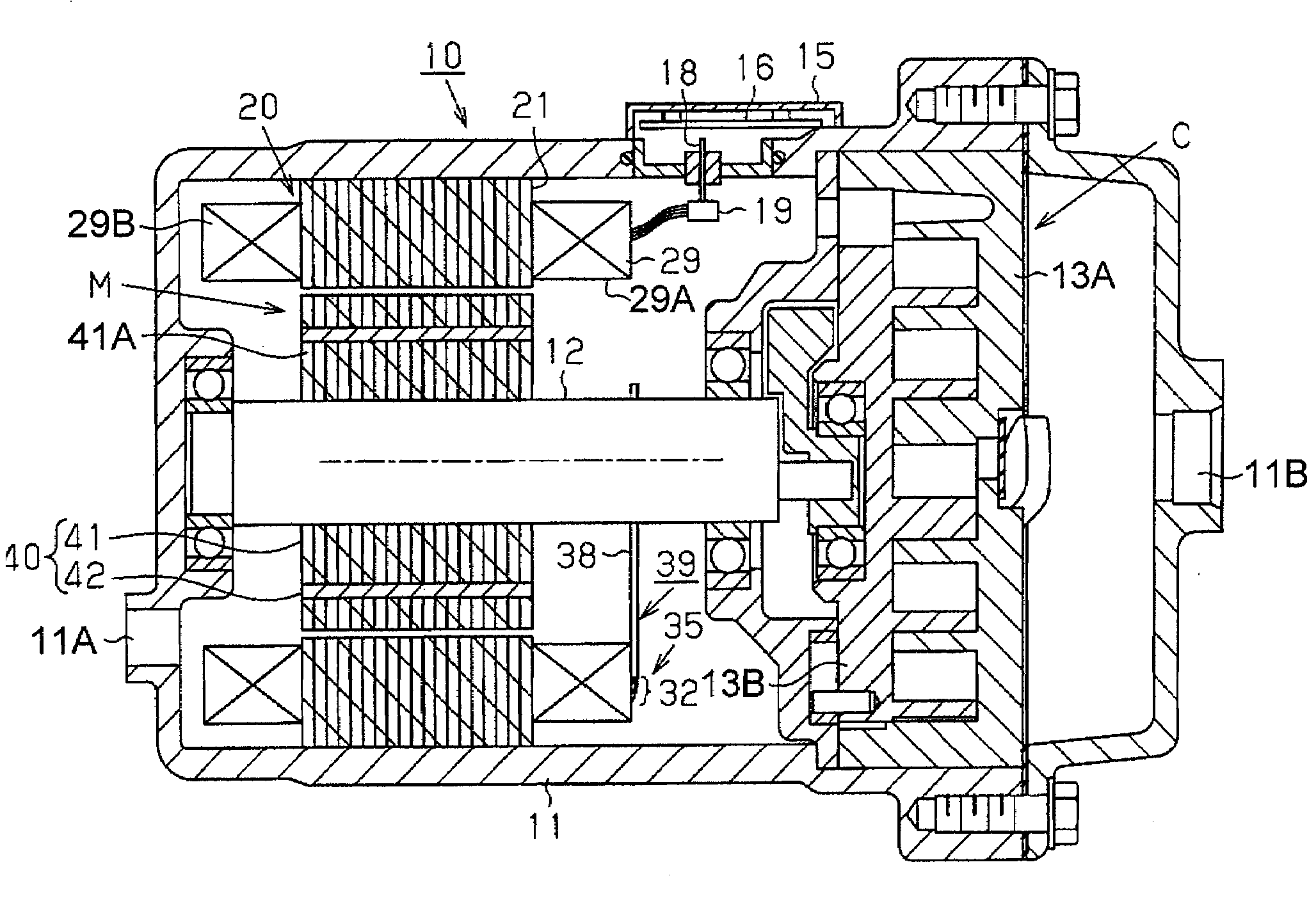
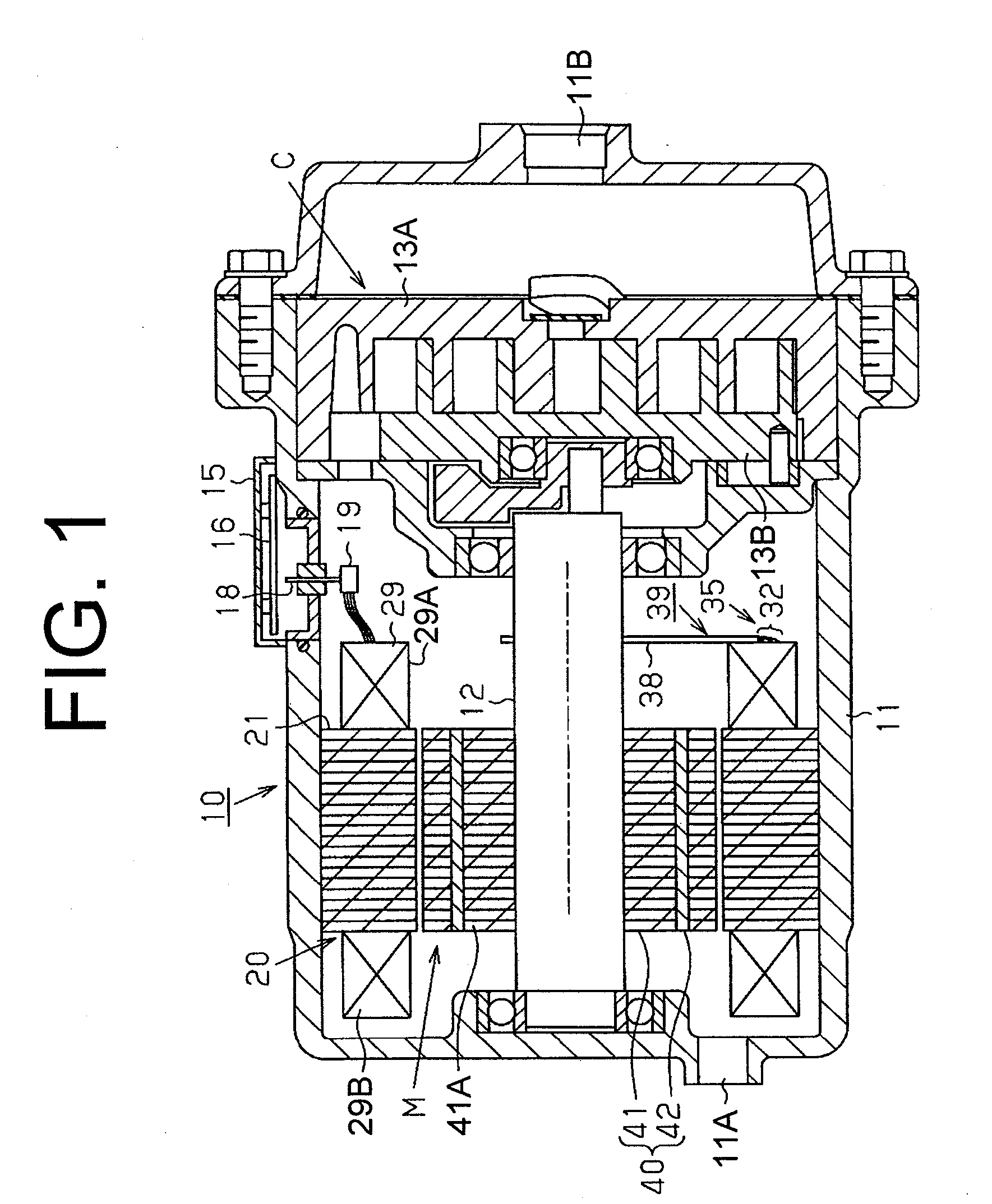
[0023]The following will describe a motor-driven compressor according to one embodiment of the present invention with reference to FIGS. 1 through 5, 6A and 6B. Referring to FIG. 1, there is shown a motor-driven compressor 10 having a housing 11 made of a die-cast metal such as aluminum alloy. A rotary shaft 12 is rotatably supported in the housing 11 and an electric motor M is housed in the housing 11 for driving to rotate the rotary shaft 12. In addition, a compression unit C which is operable to compress refrigerant gas in accordance with the rotation of the rotary shaft 12 is housed in the housing 11.

[0024]The compression unit C is of a scroll type, including a fixed scroll 13A and a movable scroll 13B. An inlet port 11A is formed in the housing 11 for allowing refrigerant gas to be drawn into the housing 11. The compression unit C is operable to compress gaseous refrigerant (or refrigerant gas) by rotating the movable scroll 13A relative to the fixed scroll 13A in accordance wi...


PUM


Abstract

An electric motor includes a cylindrical stator that is formed with a plurality of slots. The cylindrical stator has polyphase coils that are formed by winding a plurality of conductive wires in the slots to have polyphase, a wire bundle and an insulating tube covering the wire bundle. Each conductive wire includes a core wire and an insulator that covering the core wire. The wire bundle has a drawing portion, a connecting portion and an elongated portion that is elongated between the drawing portion and the connecting portion for increasing creepage distance between the connecting portion and the housing thereby to increase insulation resistance. The connecting portion of the wire bundle provides a neutral point of the electric motor. The elongated portion and the connecting portion of the wire bundle are covered with the insulating tube.

Description

BACKGROUND OF THE INVENTION[0001]The present invention relates to a motor-driven compressor having a metal housing, an electric motor housed in the metal housing and a compression unit also housed in the metal housing and compresses refrigerant by being driven by the electric motor, wherein a neutral point of the electric motor is formed by a connecting portion that connects core wires of polyphase coils of the electric motor.[0002]Metal housing of a motor-driven compressor generally houses therein not only an electric motor but also a compression unit compresses refrigerant by being driven by the electric motor. In such a motor-driven compressor, the refrigerant circulates through the compressor in gaseous form during its normal operation. When the compressor is stopped and the gaseous refrigerant in the housing is cooled, however, the refrigerant may be liquefied and collected in the housing in the form of a liquid. The liquid refrigerant has a lower specific resistivity than the ...

Claims


Application Information

Patent Timeline
Patent Type & Authority Applications(United States)
IPC IPC(8): F04B35/04
CPCF04C18/0215F04C23/008H02K3/50F04C2240/803F04C2240/808F04C29/0085
Inventor FUKASAKU, HIROSHISUITOU, KEN
Owner TOYOTA IND CORP
Why Eureka
Try Eureka