Auxiliary locomotive engine warming system

a technology for auxiliary locomotives and engine components, applied in the field of locomotives, can solve the problems of diesel engines consuming a substantial amount of fuel, locomotives may not be able to start properly, and block cracks, so as to prevent damage to the locomotive engine, and install quickly and easily into the locomotive

a technology for auxiliary locomotives and engine components, applied in the field of locomotives, can solve the problems of diesel engines consuming a substantial amount of fuel, locomotives may not be able to start properly, and block cracks, so as to prevent damage to the locomotive engine, and install quickly and easily into the locomotive

US20090272353A1Inactive Publication Date: 2009-11-05POWER DRIVES

Image

  • Auxiliary locomotive engine warming system
  • Auxiliary locomotive engine warming system
  • Auxiliary locomotive engine warming system

Examples


Embodiment Construction

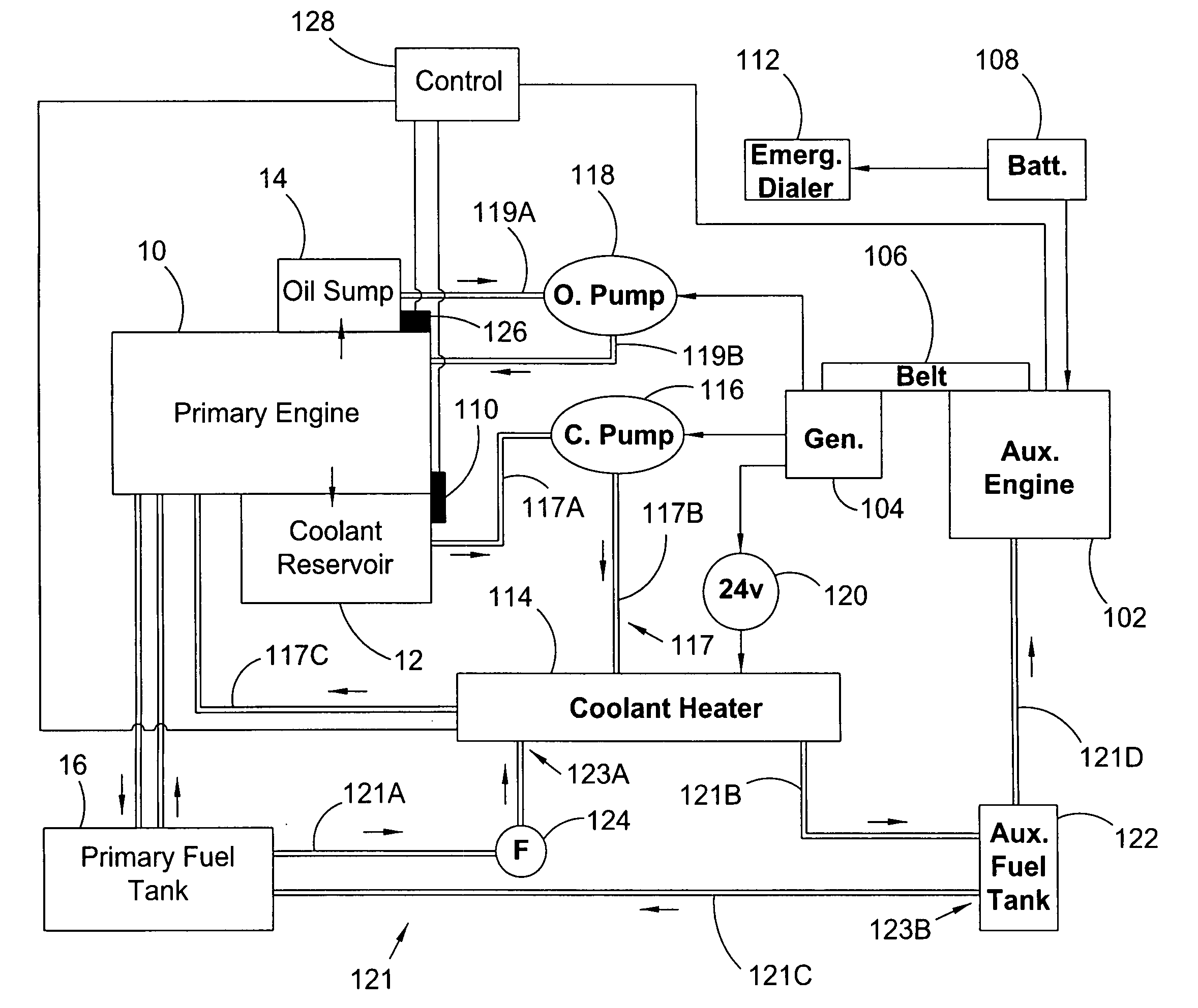
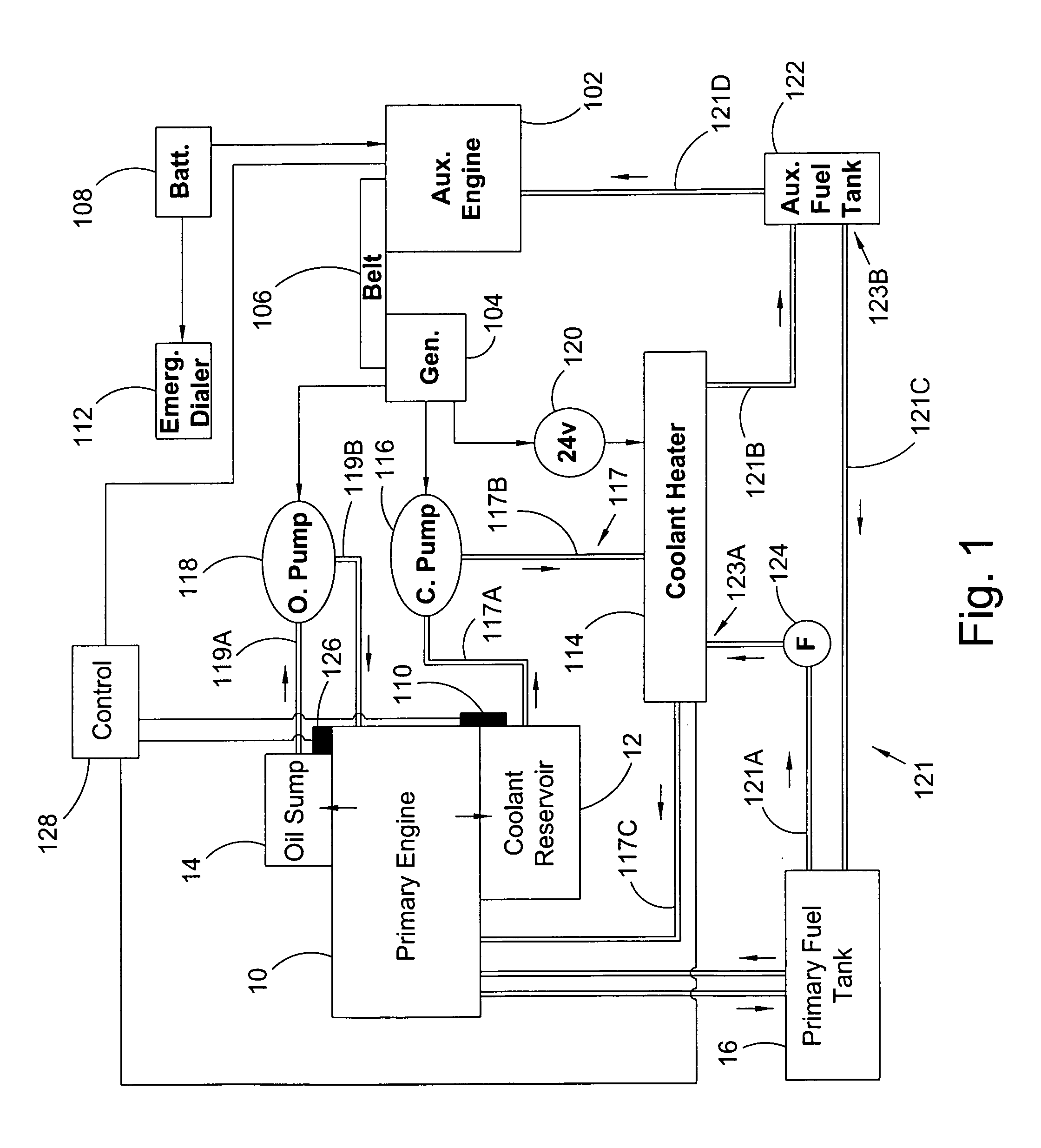
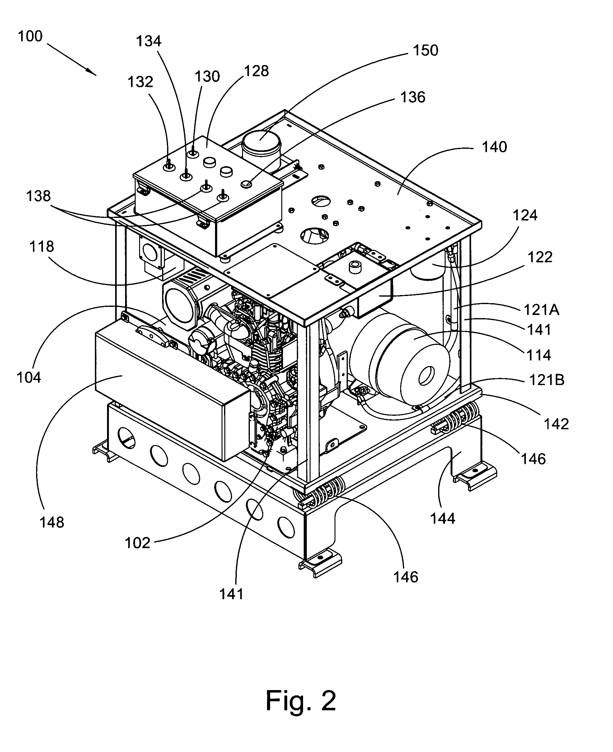
[0023]At the outset, it should be appreciated that like drawing numbers on different drawing views identify identical, or functionally similar, structural elements of the invention. While the present invention is described with respect to what is presently considered to be the preferred aspects, it is to be understood that the invention as claimed is not limited to the disclosed aspects.

[0024]Furthermore, it should be understood that this invention is not limited to the particular methodology, materials and modifications described and as such may, of course, vary. It should also be understood that the terminology used herein is for the purpose of describing particular aspects only, and is not intended to limit the scope of the present invention, which is limited only by the appended claims.

[0025]Unless defined otherwise, all technical and scientific terms used herein have the same meaning as commonly understood to one of ordinary skill in the art to which this invention belongs. Alt...


PUM


Abstract

An auxiliary engine warming system for a primary engine in a diesel locomotive including: a modular engine assembly including an auxiliary diesel engine, the assembly displaceable as a unit from and to a frame for the engine warming system; an auxiliary fuel tank including a fuel line detachably connected to the auxiliary engine and including a first fitting detachably connectable to a first fuel line for a fuel tank for the diesel; at least one temperature sensor interfacable with the diesel locomotive and arranged to monitor at least one temperature condition for the diesel locomotive; and an emergency dialer for automatically dialing a preprogrammed number and transmitting an alert message in response to an alarm signal from the at least one temperature sensor.

Description

FIELD OF THE INVENTION[0001]This invention relates to locomotives, and more specifically to an improved auxiliary locomotive engine warming system.BACKGROUND OF THE INVENTION[0002]Traditionally, when temperatures approach freezing, locomotives are left idling to keep their diesel engines heated, to both prevent damage from freezing and to facilitate a re-start. This includes keeping locomotives running over entire weekends, or in some cases, even longer periods of time, as necessary. If the diesel engines are not kept warm, the engine blocks may crack from freezing, or the locomotive may not be able to start properly. Even while idling, diesel engines consume a substantial amount of fuel, especially in the case of large locomotive engines. Moreover, the rising costs of diesel and other fuels, along with trends towards making products more eco-friendly, have drastically increased the desirability of reducing fuel consumption whenever possible. Therefore, auxiliary warming systems hav...

Claims


Application Information

Patent Timeline
05 Nov 2009
Publication
US20090272353A1
IPC
F02N17/04; F02N19/04
CPC
F02N19/04; F02N15/10
Inventors
GATES, BRADLEY R.; GROSS, BRIAN D.