

Reinforcement structure for pipe and cab structure for construction machine having the same
a technology of cab structure and reinforcement structure, which is applied in the direction of roofs, couplings, transportation and packaging, etc., can solve the problems of increased cost and high cost of pipe reinforcement, and achieve the effect of preventing marring the appearance of cab structure and highly strong cab structur
- Summary
- Abstract
- Description
- Claims
- Application Information
AI Technical Summary
Benefits of technology
Problems solved by technology
Method used
Image

Examples
first embodiment
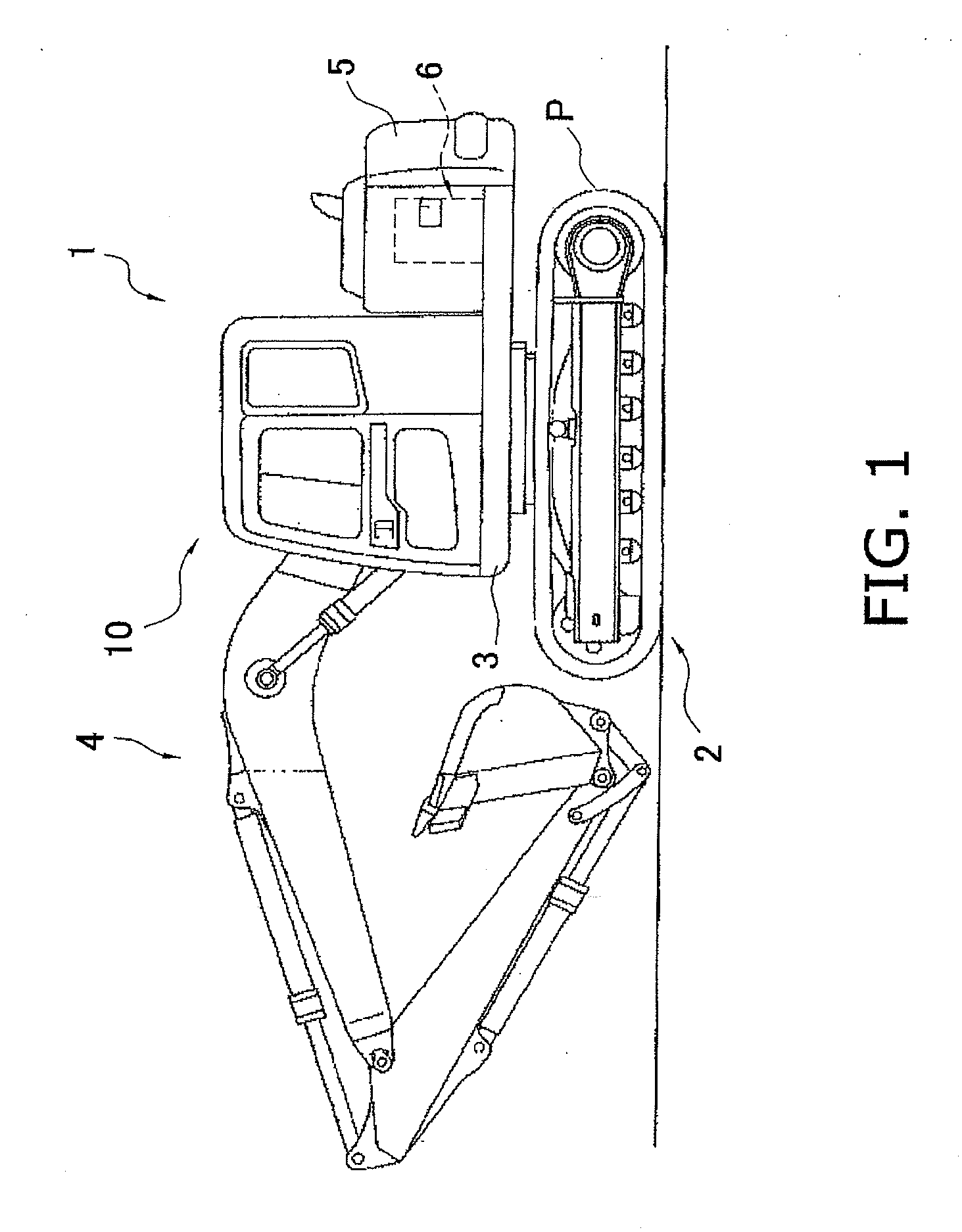
[0085]With reference to FIG. 1 to FIG. 5(b), the following description will describe a hydraulic excavator 1 that includes a cab 10 to which a reinforcement structure for a pipe according to one embodiment of the present invention is adopted.
[0086]As used herein to describe the present invention, terms “left and right”, “front and rear”, and “front-side surface and rear-side surface” should be interpreted as directions relative to an operator when sitting on a seat in the cab 10 (see FIG. 1, for example).
Overall Configuration of Hydraulic Excavator 1
[0087]The hydraulic excavator 1 according to this embodiment includes a lower traveling unit 2, a revolving base 3, a working unit 4, a counterweight 5, an engine 6, and the cab 10, as shown in FIG. 1.
[0088]The lower traveling unit 2 drives endless belts P that are wounded on the left and right sides of the lower tractor portion 2 relative to the advance direction so that the hydraulic tractor shovel 1 moves frontward and rearward. The r...
second embodiment
[0121]With reference to FIG. 11 to FIG. 17, the following description will describe a reinforcement structure for a pipe 120 according to another embodiment of the present invention.
[0122]Note that, in description of this embodiment, components that have shapes and functions similar to the components described in the foregoing embodiment are attached with the same reference numerals and their description is omitted.
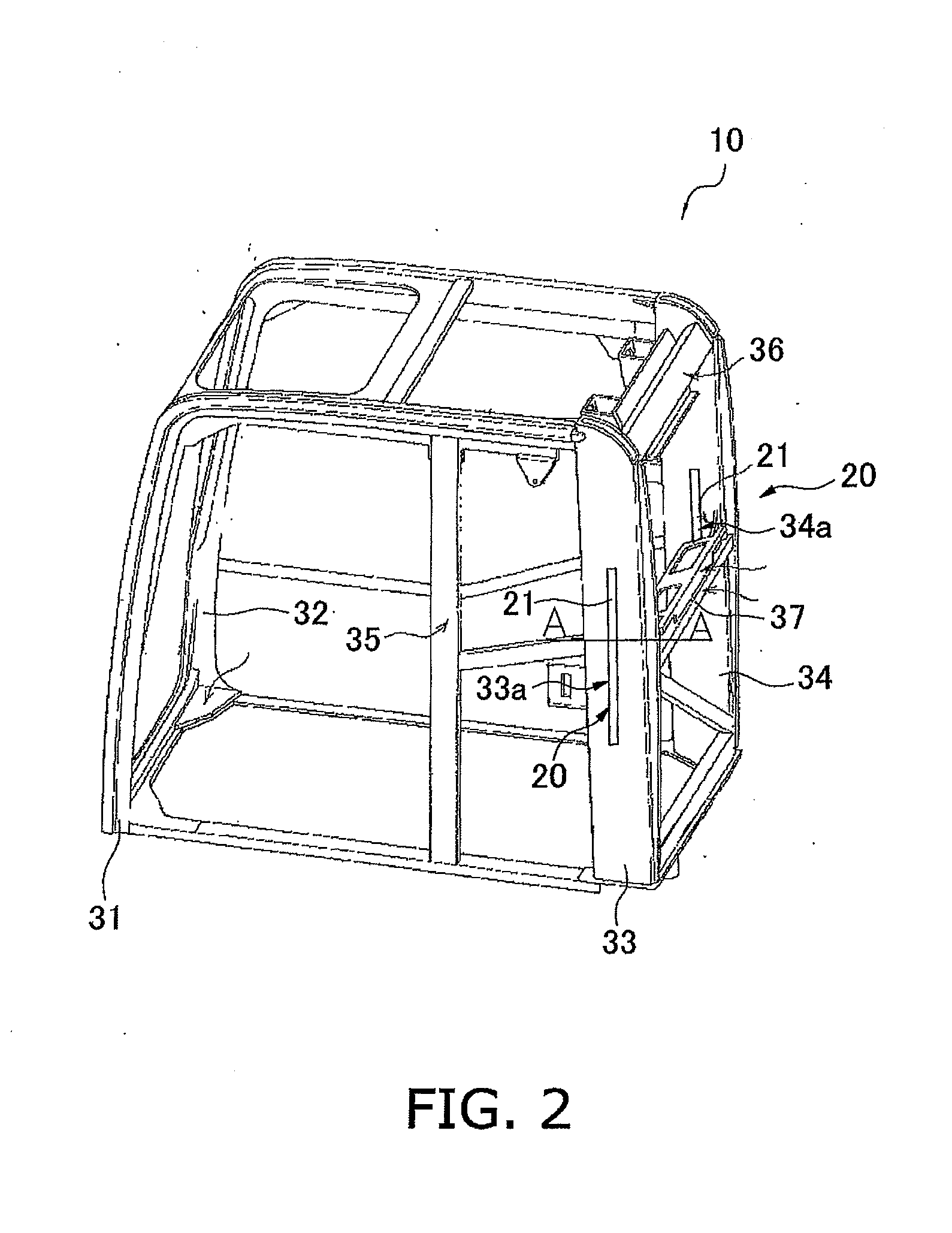
[0123]That is, as shown in FIG. 11, among a plurality of pole members 31, 32, 133, 134 and 35 that compose a cab 110, the reinforcement structure 120 according to this embodiment is provided for the rear left and right pole member 133 and 134.
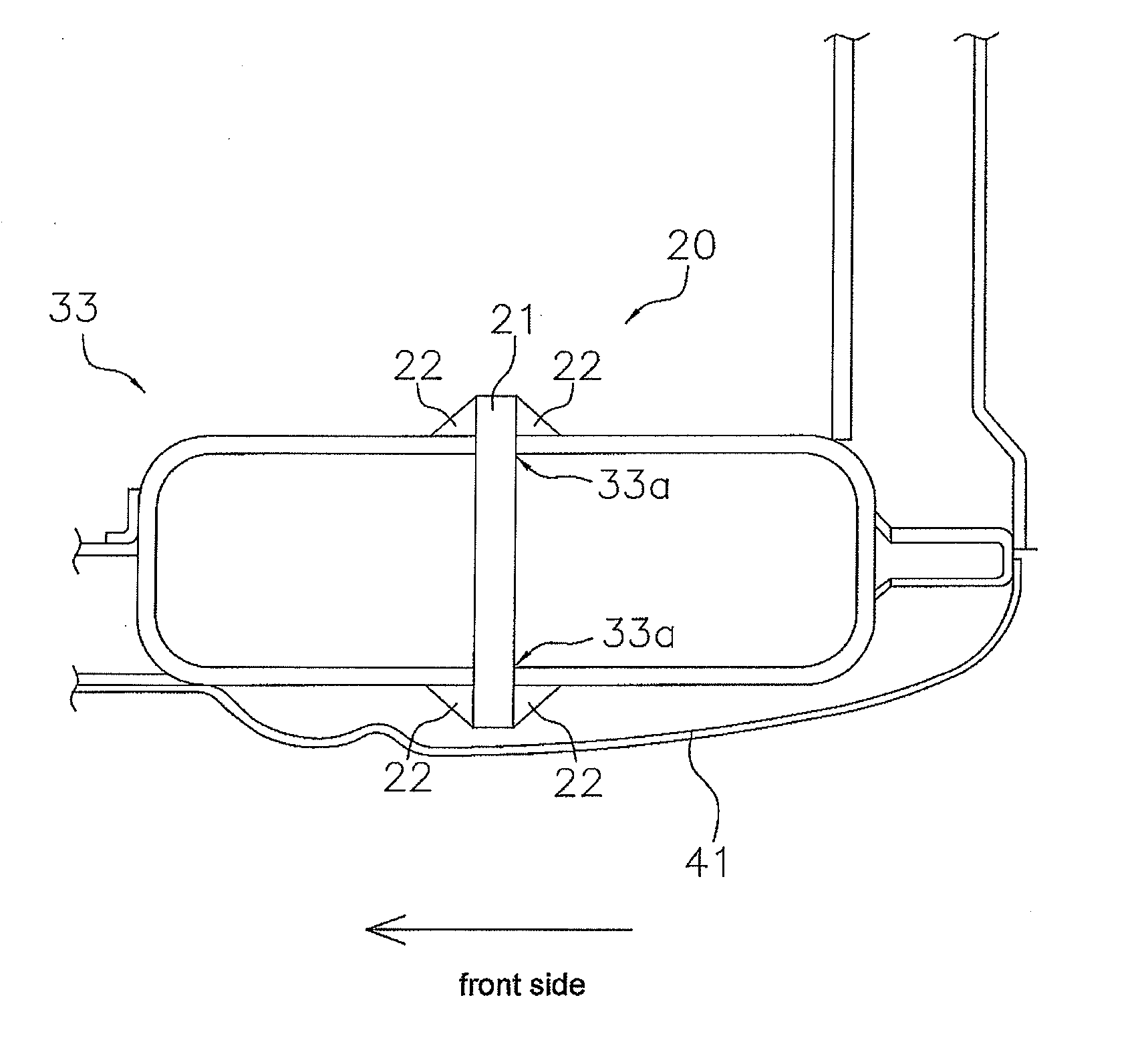
[0124]Specifically, as shown in FIG. 12, in the reinforcement structure 120 that is provided for the rear left pole member (pole member) 133, a plate member 121 is secured to the rear left pole member 133 in the state where protruding portions 121a that are formed on the insertion-side end surface of the plate member 121 (see FIG. 16...
examples
[0174]For the reinforcement structure for a pipe 20 according to the foregoing embodiment that is applied to the pole members 33 and 34 that compose the cab 10 that is installed on the hydraulic excavator 1, experiment was conducted to provide how the changes of the size and the insertion position of the plate member 21 that is inserted in the hole sections 33a or the like that are formed on the outer peripheral surfaces of the pole members 33 and 34 exert influences upon the strength of the cab 10. The results will be described.
[0175]The description describes the results of EOPS test that provide the degree of deformation of the cab 10 (relationship between load and displacement amount) when a load is applied to the cab 10 that is installed on the revolving base 3 in a direction from the left surface to the working portion 4.
[0176]FIG. 8 shows a graph showing, in the case where the entire length (length in a direction perpendicularly intersects the insertion direction) of the plate...
PUM
 Abstract
Description
Claims
Application Information