Enhanced wireless eddy current probe for a non-destructive inspection system

a non-destructive technology, applied in the direction of instruments, magnetic property measurements, material magnetic variables, etc., can solve the problems of inconvenient inspection, easy damage, and complex interconnection probe cables, and achieve the effect of enhancing wireless eddy current probes

Active Publication Date: 2009-11-05
OLYMPUS NDT
View PDF3 Cites 13 Cited by
  • Summary
  • Abstract
  • Description
  • Claims
  • Application Information

AI Technical Summary

Benefits of technology

[0011]It is the object of the present disclosure to overcome the problems associated with prior art. This is attained by introducing the enhanced wireless eddy current probe of the present disclosure. In the preferred embodiment of the present disclosure, the enhanced wireless eddy current probe comprises a wireless transceiver element with means to both transmit and receive signals from a similar wireless transceiver element within to a non-destructive inspection (NDI) system, a microcontroller, a nonvolatile memory element...

Problems solved by technology

In many inspection systems, due to the plurality of connections required between the eddy current probe and the NDI system, the interconnecting probe cable becomes complex, expensive, and, in many cases, prone to damage.
Moreover, in many NDI inspection operations one or more inspection points are located in difficult to access locations.
Within such an inspection operation, the length of the interconnecting probe cable—often constrained by cost and signal integrity restrictions—can become a significant limitation for said operation.
While Filkins teaches a system which effectively overcomes the limitations of probe cable length, his solution is limited to and strictly addresses an ultrasonic system and is limited to an “uplink” path (a wireless communication path which provides means for signal transfer from an NDI system to an ultrasonic inspection probe) which transmits “timing pulse signals” to the ultrasonic probe and a “downlink” path (a wireless communication path which provides means for signal transfer from an ultrasonic inspection probe to...

Method used


Image

  • Enhanced wireless eddy current probe for a non-destructive inspection system
  • Enhanced wireless eddy current probe for a non-destructive inspection system
  • Enhanced wireless eddy current probe for a non-destructive inspection system

Examples


Embodiment Construction

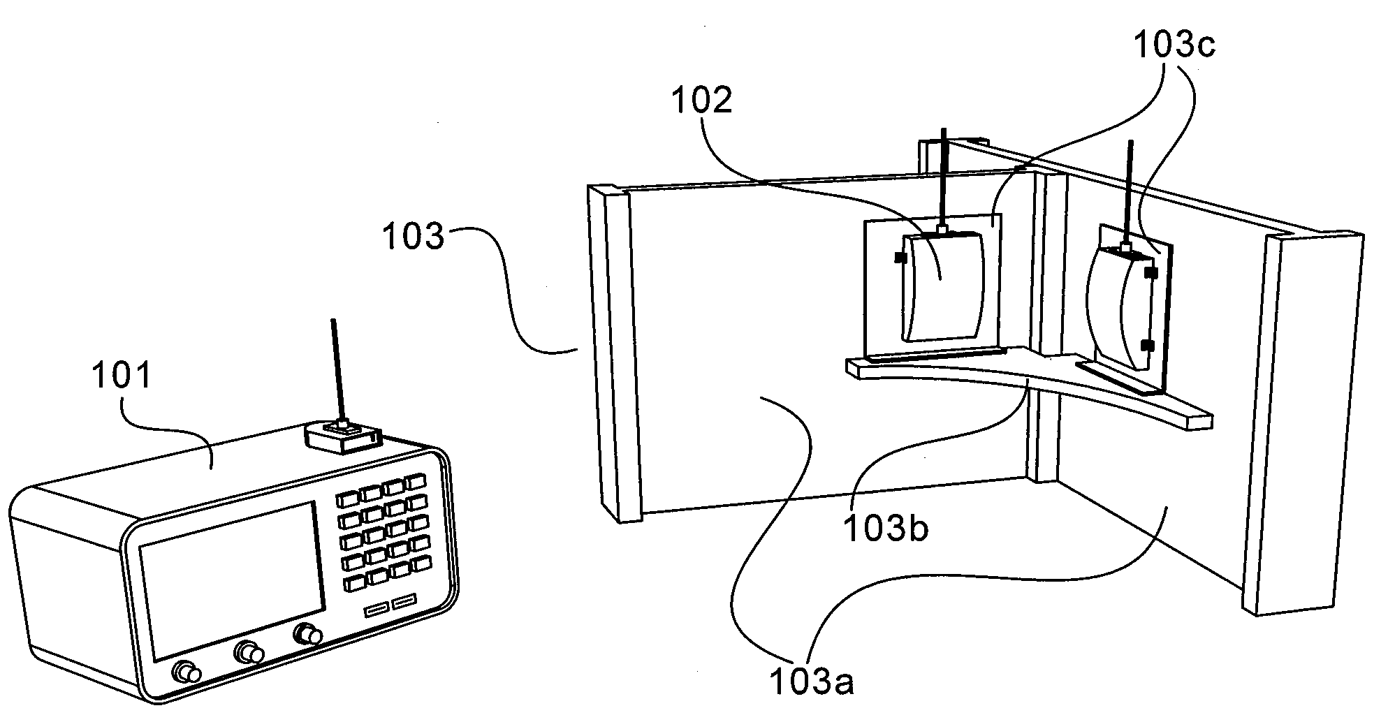
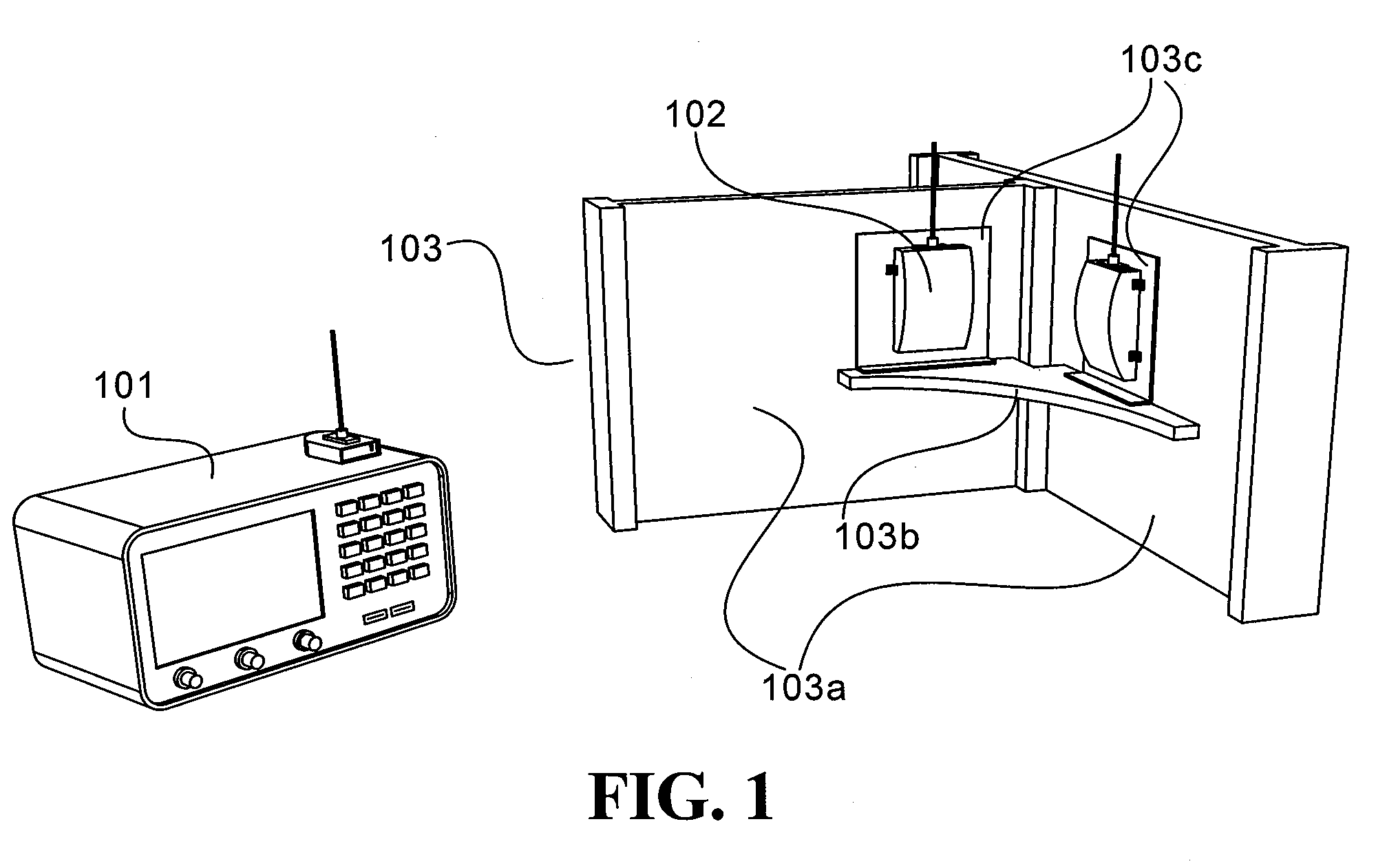
[0027]FIG. 1 is a perspective drawing illustrating an exemplary non-destructive inspection (NDI) operation which makes use of the enhanced wireless eddy current probe of the present disclosure. An NDI system 101 is situated some distance away from a structure under inspection 103. Said structure 103 is comprised of a pair of support beams 103a, a bracing element 103b, and a pair of mounting brackets 103c. In this exemplary structure 103, said mounting brackets 103c are welded to the support beams 103a to hold bracing element 103b in place. In the exemplary NDI operation depicted in FIG. 1, the integrity of the welds fixing the mounting brackets 103c to the support beams 103a is the subject of the inspection. As such, an enhanced wireless eddy current probe 102 has been mounted over each weld point.

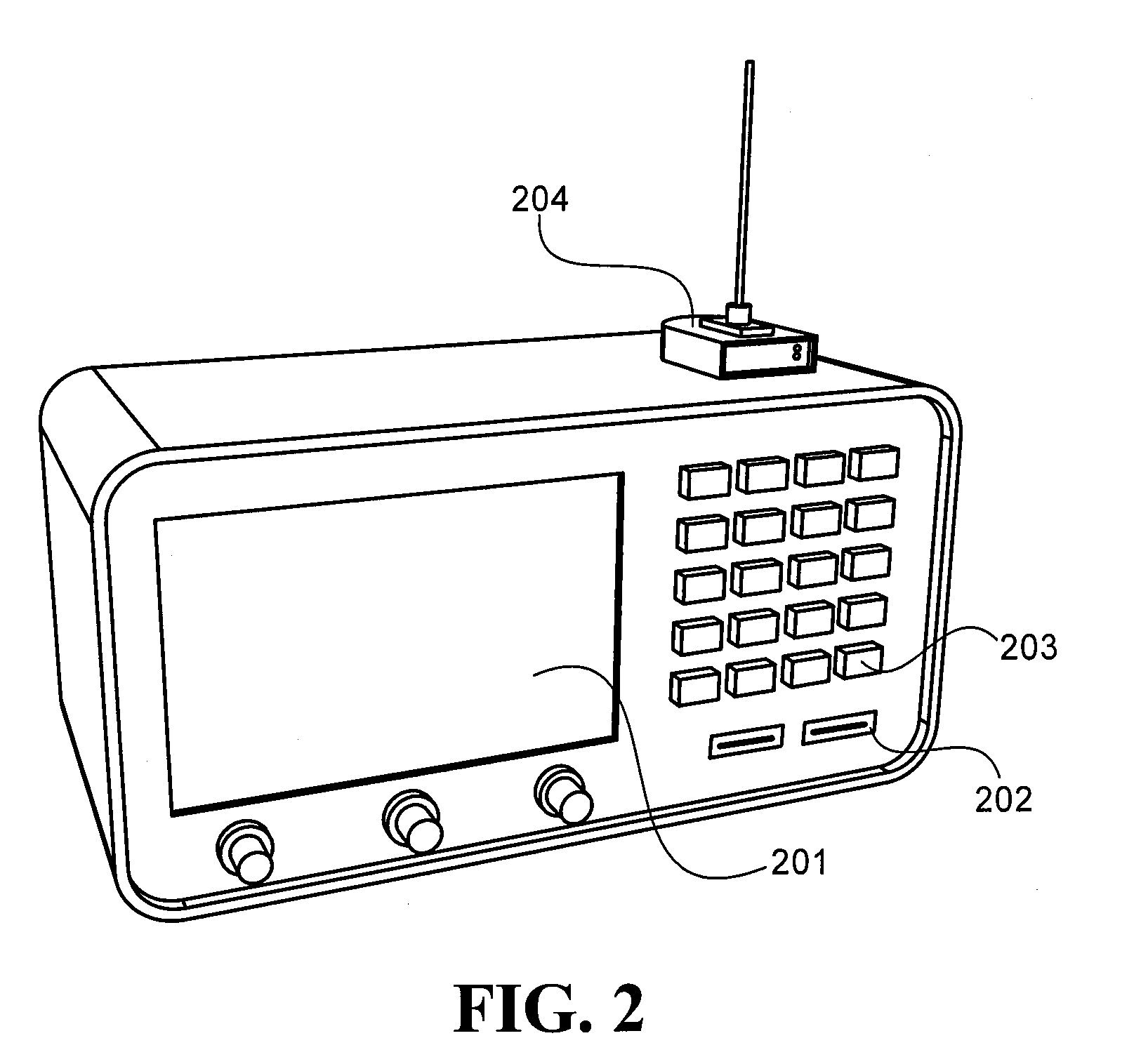
[0028]FIG. 2 is a perspective drawing illustrating the NDI system used in the NDI operation depicted in FIG. 1. A functional block diagram of this NDI system is detailed in FIGS. 4A-4C. Th...


PUM


Abstract

An enhanced wireless eddy current probe is disclosed which has means to wirelessly couple to a non-destructive inspection (NDI) system situated some distance away from an inspection point on a material under inspection. The disclosed enhanced wireless eddy current probe provides means for executing advanced functions necessary for a complex eddy current inspection operation. These functions include, but are not limited to, storing, loading, and executing a predetermined firing sequence on an array of coil elements, probe balancing, probe calibration, and providing bibliographic information specific to said probe to a wirelessly coupled NDI system.

Description

CROSS REFERENCE TO RELATED APPLICATIONS[0001]This application is a continuation-in-part of U.S. patent application Ser. No. 12 / 425,976 filed Apr. 17, 2009 entitled AN ENHANCED WIRELESS EDDY CURRENT PROBE FOR A NON-DESTRUCTIVE INSPECTION SYSTEM which claims the benefit and priority of U.S. Provisional patent application Ser. No. 61 / 046,011, filed Apr. 18, 2008, entitled AN ENHANCED WIRELESS EDDY CURRENT PROBE FOR USE WITHIN A NON-DESTRUCTIVE INSPECTION SYSTEM. This application also claims the benefit and priority of U.S. Provisional patent application Ser. No. 61 / 081,842, filed Jul. 18, 2008 entitled AN ENHANCED WIRELESS EDDY CURRENT PROBE FOR USE WITHIN A NON-DESTRUCTIVE INSPECTION SYSTEM, the entire disclosures of which are incorporated herein by reference.BACKGROUND OF THE INVENTION[0002]The present invention relates to non-destructive inspection (NDI) instruments, and more particularly to an enhanced wireless eddy current probe which provides advanced functionality including embe...

Claims


Application Information

Patent Timeline
IPC IPC(8): G01N27/90
CPCG01N27/90
Inventor DRUMMY, MICHAEL
Owner OLYMPUS NDT
Why Eureka
Try Eureka