
Multiple antenna arrangement

a multi-antenna and antenna technology, applied in the direction of antennas, radiating element structural forms, resonance antennas, etc., can solve the problems of affecting the development of diversity antennas the volume of diversity antennas is too large for modern compact handheld devices to achieve high isolation, and the bandwidth of bandwidth is a function of antenna volume, so as to achieve compact size and improve isolation

Inactive Publication Date: 2009-11-05
NXP BV
View PDF4 Cites 42 Cited by
  • Summary
  • Abstract
  • Description
  • Claims
  • Application Information

AI Technical Summary

Benefits of technology

[0008]An object of the invention is to provide improved apparatus or methods.
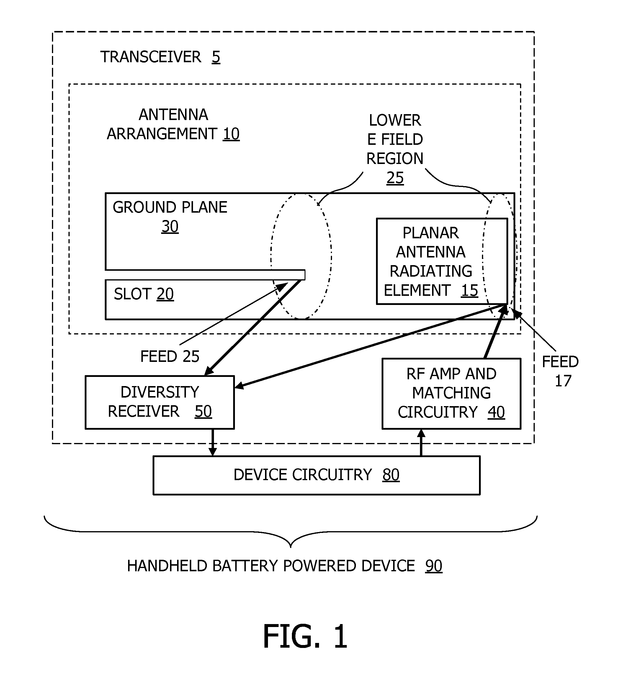
[0009]According to a first aspect of the invention there is provided an antenna arrangement having a ground plane, a planar antenna, and a slot antenna in the form of a slot in the ground plane, the planar antenna and the slot antenna being arranged to radiate or receive with different polarisations, the ground plane having higher and lower E field regions, caused by use of either of the antennas, and a feed of at least one of the antennas being located in the lower E field region caused by the other of the antennas.
[0010]This combination of different types of antenna can provide relatively well defined lower E field regions in a relatively compact size. This means that proper location of either or both f...

Problems solved by technology

However, there are the fundamental limits on bandwidth as a function of antenna volume.
However, many issues are associated with adoption of diversity antennas inside handheld devices.
One is that the volume of diversity antennas is too large for modern compact handheld devices to achieve a high isolation and low cross-correlation coefficient, particularly in the GSM900 / 800 bands.
In “A compact planar polarisation diversity antenna for mobile communication” by Yu, Wang and Wu, p 682-685, 0-7803-7846-6 / 6 / 03, IEEE, it is reported that the development of a diversity antenna for modern compact handsets is a significant challenge due to the conflicting requirements imposed on the antenna, such as compactness, bandwidth, efficiency, and isolation between the feed ports.

Method used


Image

  • Multiple antenna arrangement
  • Multiple antenna arrangement
  • Multiple antenna arrangement

Examples


Embodiment Construction

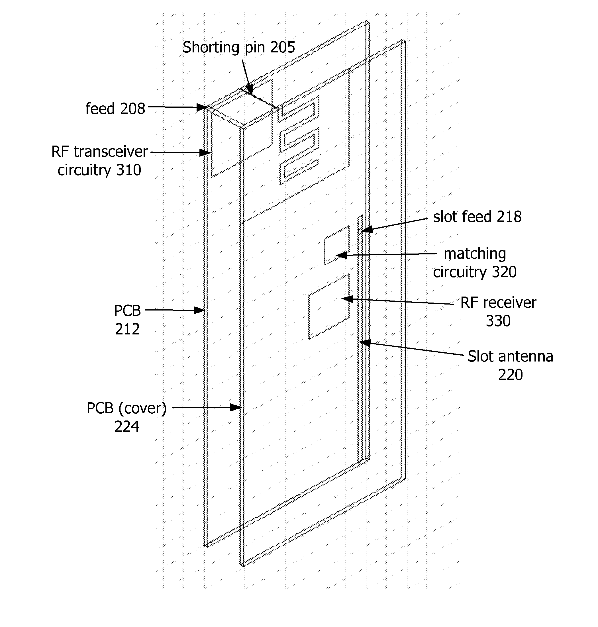
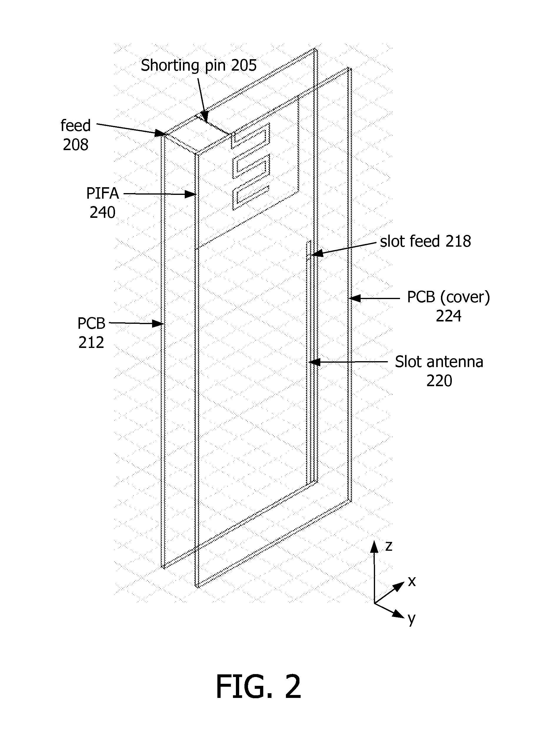
[0019]In at least some of the embodiments of this invention, two antennas have been built into a handheld device; a planar antenna and a quarter-wavelength slot antenna. The feed of the slot antenna is placed in a lower E field region, such as on a minimum E-field line excited by the planar antenna. The open end of the slot is pointed away from the planar antenna so that the feed of the planar antenna is located at the lower E-field area of the slot antenna. The polarisation of the slot antenna is different by being orthogonal or nearly orthogonal, to that of the planar antenna, so as to create some isolation, for example greater than 15 dB.

[0020]Polarisation diversity can be achieved in principle by using a half-wavelength antenna (or two half-wavelength antennas) or two quarter-wavelength antennas. The former solution is too big for modern hand-held devices, but with the latter solution it is difficult to achieve a good isolation in practice (for example greater than 15 dB), while...


PUM


Abstract

An antenna arrangement having a ground plane (30, 212) a PIFA antenna (15, 240) arranged parallel to the ground plane, and a quarter wave slot antenna (220), arranged to radiate or receive with orthogonal polarisations, the ground plane being rectangular and having higher and lower E field regions (25), caused by use of either of the antennas. The feed (205, 218) of at least one of the antennas is located in the lower E field region caused by the other of the antennas, to provide improved isolation for a compact size. This can be useful for diversity or dual band use, for mobile handset devices.

Description

TECHNICAL FIELD[0001]This invention relates to antenna arrangements and to devices having such antenna arrangements.BACKGROUND ART[0002]Modern mobile phone handsets and other portable devices typically incorporate an internal antenna, such as a Planar Inverted-F Antenna (PIFA) or other planar antenna, or similar. Planar inverted F-antennas in mobile terminals are used to cover an increasing number of communications bands, such as CDMA850, GSM900, GSM1800, PCS1900, and UMTS2000. At the same time, the size of mobile terminals has been reduced dramatically. The miniaturisation of mobile terminals leaves ever less space for the antenna. However, there are the fundamental limits on bandwidth as a function of antenna volume. Generally speaking, the smaller the antenna size, the narrower the bandwidth.[0003]In addition, modern handheld devices are required to cover an increasing number of communications systems. Therefore, more than one antenna has been or will be introduced into handheld ...

Claims


Application Information

Patent Timeline
IPC IPC(8): H01Q21/00H01Q9/04H01Q13/10
CPCH01Q1/243H01Q13/10H01Q9/0421
Inventor LIU, ZIDONG
Owner NXP BV
Learn More