Measuring Device with Two-channel Sampling

Inactive Publication Date: 2009-11-05
BAUMER ELECTRIC
View PDF4 Cites 24 Cited by
  • Summary
  • Abstract
  • Description
  • Claims
  • Application Information

AI Technical Summary

Problems solved by technology

In the applications of shaft encoders which are sometimes very demanding as regards ambient conditions, soiling and/or wear effects can result in non-tolerable faulty measurements or even a partial or total failure of a shaft encoder.
The techni

Method used


Image

  • Measuring Device with Two-channel Sampling
  • Measuring Device with Two-channel Sampling
  • Measuring Device with Two-channel Sampling

Examples


Embodiment Construction

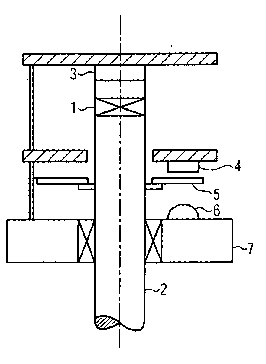
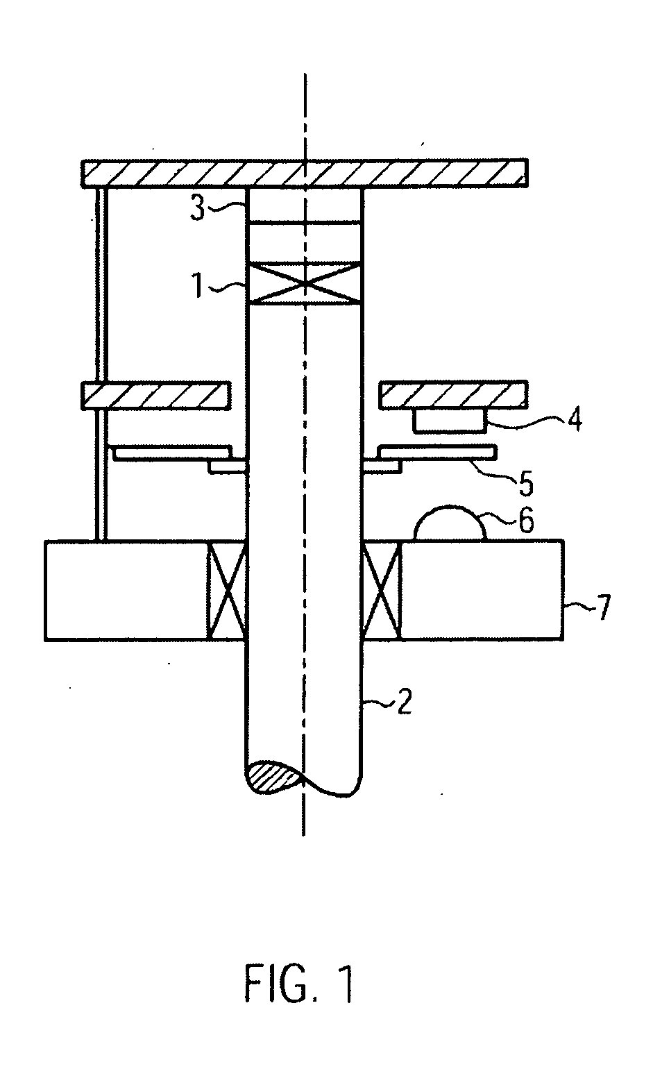
[0006]The above-mentioned object is achieved by the shaft encoder (rotary encoder) device for sampling a rotating shaft according to claim 1, comprising

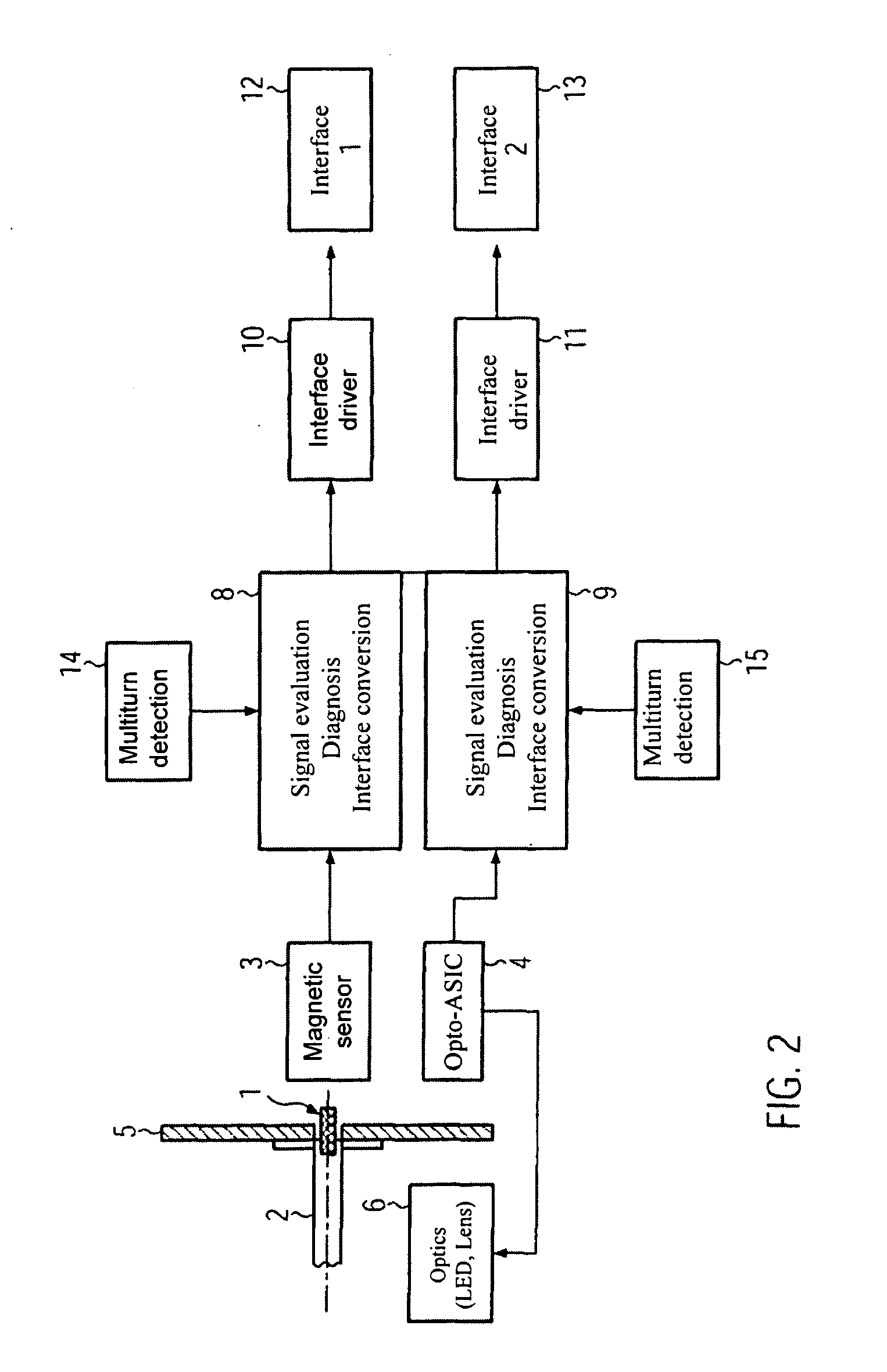
magnetic sensor means designed to detect the magnetic field of magnetic field generating means stationary with respect to the shaft and in particular fixed thereto;

a light source;

optical sensor means designed to detect light emitted from the light source and reflected or transmitted by an encoder disk stationary with respect to the shaft and in particular fixed thereto; and

signal processing means designed to receive first data from the magnetic sensor means and second data from the optical sensor means and to determine an angle of rotation of the shaft from the received first data and / or to determine the angle of rotation of the shaft from the received second data.

[0007]The concept “shaft” herein comprises a rotating, merely mechanically or electrically driven axle, and also in general any rotating, straight, curvilinear or helical s...


PUM


Abstract

The present invention relates to a shaft encoder device, comprising magnetic sensor means designed to detect the magnetic field of a magnetic field generating means stationary with respect to the shaft, a light source, optical sensor means designed to detect light emitted from the light source and reflected or transmitted by an encoder disk stationary with respect to the shaft, and signal processing means designed to receive first data from the magnetic sensor means and second data from the optical sensor means, and to determine an angle of rotation of the shaft from the received first data and/or to determine the angle of rotation of the shaft from the received second data.

Description

FIELD OF THE INVENTION[0001]The present invention relates to a measuring device for determining the position and / or the angle of rotation of a body that carries out a translatory and / or a rotary motion, in particular a shaft encoder for measuring the rotation of a shaft rotating about an axis of rotation, and furthermore in particular a two-channel sampling of a rotating shaft for securely determining the angle of rotation of the shaft.BACKGROUND OF THE INVENTION[0002]Measuring devices, such as shaft encoders for determining angular positions of moving axes or shafts by contactless single or multiturn sampling, are already generally used for monitoring and controlling mechanical motion sequences. Shaft encoders are, for example, employed for detecting the speed of motors and controlling the same, for the open-loop or closed-loop control of transport systems, or for monitoring conveyor belts. However, recently the demands on the accuracy, and in particular on the reliability, of the ...

Claims


Application Information

Patent Timeline
IPC IPC(8): G01B7/30G01B11/26G06F15/00
CPCG01B21/22G01D5/145G01D5/58G01D5/56G01D5/3473
Inventor SCHNEIDER, MICHAELBRUGGER, PETERTARRAF, AMER
Owner BAUMER ELECTRIC
Why Eureka
Try Eureka