Measuring device with two-channel sampling

a two-channel sampling and measuring device technology, applied in the direction of speed measurement using gyroscopic effects, speed/acceleration/shock measurement devices, testing/calibration of speed/acceleration/speed, etc., can solve the problems of inability to incorporate several housings for individual measuring means, and inability to meet the requirements of measurement accuracy. , to achieve the effect of increasing redundancy

Inactive Publication Date: 2012-08-07
BAUMER ELECTRIC
View PDF7 Cites 5 Cited by
  • Summary
  • Abstract
  • Description
  • Claims
  • Application Information

AI Technical Summary

Benefits of technology

[0020]The magnetic sensor means is, for example, relatively insensitive with respect to local dirt deposits and impacts on the shaft. However, magnetic interference fields can have a negative influence on the accuracy of the measurement. On the other hand, the accuracy of measurement of the angle of rotation by means of the encoder disk stationary with the shaft can suffer in case of irregular impacts of the shaft and dirt deposits on the shaft. If there are no such disturbances, very fine bar codes that can be vapor-deposited, etched or printed onto an encoder disk made of glass, plastics or metal material, permit high measurement resolutions.
[0032]In this shaft encoder device according to the invention, as well as in the above-described further embodiments of the shaft encoder device with optical and magnetic sensor means, in each case more than two of the corresponding sensor (detection) means can be included and used to further increase redundancy. In particular, three or more sensor (detection) means can be included which each realize different physical measuring methods.

Problems solved by technology

In the applications of shaft encoders which are sometimes very demanding as regards ambient conditions, soiling and / or wear effects can result in non-tolerable faulty measurements or even a partial or total failure of a shaft encoder.
The technical efforts as well as the costs for a shaft encoder system are naturally significantly increased thereby.
Moreover, the incorporation of several housings for individual measuring means can be constructionally disadvantageous or even impossible.

Method used


Image

  • Measuring device with two-channel sampling
  • Measuring device with two-channel sampling
  • Measuring device with two-channel sampling

Examples


Embodiment Construction

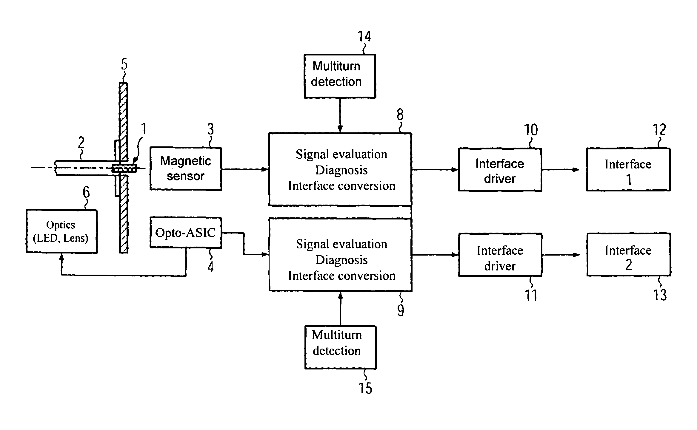
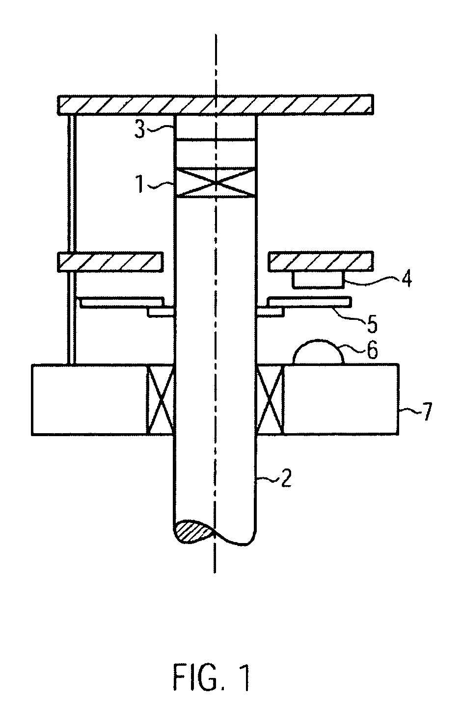
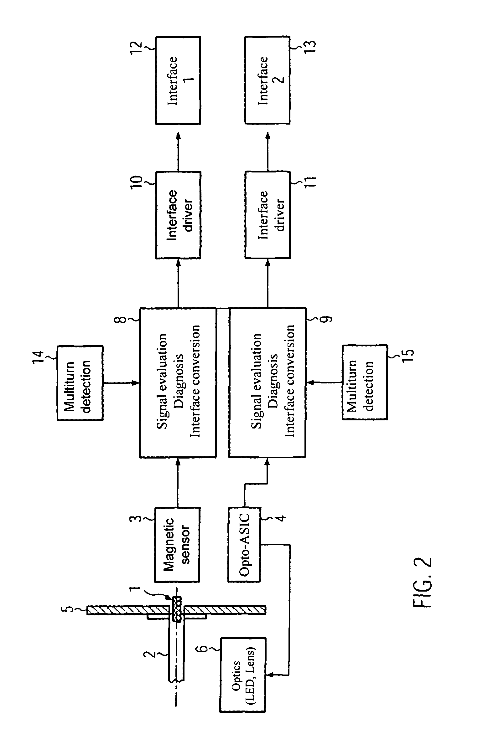
[0049]In the example illustrated in FIG. 1, a shaft encoder according to the invention for sampling a rotating shaft 2 provided with a magnet 1 comprises a magnetic sensor 3, an optical sensor 4 with a user-specific circuit, an encoder disk 5 connected to the shaft 2, and a light source 6 attached to a flange 7 in which the shaft 2 is rotatably mounted. The light source 6 can comprise an LED or an incandescent lamp or the like as well as one or several lenses, and light within or outside (e.g. infrared or ultraviolet) the visible spectrum can be emitted from this light source 6.

[0050]In particular, in the shown example, the magnetic 3 and optical 4 sensors as well as the encoder disk 5 and the light source 6 are completely located in one single housing, so that the construction can be advantageously designed as concerns space requirements and compactness.

[0051]In the shown example, light emitted from the light source 6 passes through apertures provided within the encoder disk 5 rota...


PUM


Abstract

The present invention relates to a shaft encoder device, comprising magnetic sensor means designed to detect the magnetic field of a magnetic field generating means stationary with respect to the shaft, a light source, optical sensor means designed to detect light emitted from the light source and reflected or transmitted by an encoder disk stationary with respect to the shaft, and signal processing means designed to receive first data from the magnetic sensor means and second data from the optical sensor means, and to determine an angle of rotation of the shaft from the received first data and / or to determine the angle of rotation of the shaft from the received second data.

Description

FIELD OF THE INVENTION[0001]The present invention relates to a measuring device for determining the position and / or the angle of rotation of a body that carries out a translatory and / or a rotary motion, in particular a shaft encoder for measuring the rotation of a shaft rotating about an axis of rotation, and furthermore in particular a two-channel sampling of a rotating shaft for securely determining the angle of rotation of the shaft.BACKGROUND OF THE INVENTION[0002]Measuring devices, such as shaft encoders for determining angular positions of moving axes or shafts by contactless single or multiturn sampling, are already generally used for monitoring and controlling mechanical motion sequences. Shaft encoders are, for example, employed for detecting the speed of motors and controlling the same, for the open-loop or closed-loop control of transport systems, or for monitoring conveyor belts. However, recently the demands on the accuracy, and in particular on the reliability, of the ...

Claims


Application Information

Patent Timeline
Patent Type & Authority Patents(United States)
IPC IPC(8): G01C1/00G01C9/00
CPCG01B21/22G01D5/145G01D5/3473G01D5/56G01D5/58
Inventor SCHNEIDER, MICHAELBRUGGER, PETERTARRAF, AMER
Owner BAUMER ELECTRIC
Why Eureka
Try Eureka