Self Activated Power Brake

a self-activated, power brake technology, applied in the direction of axially engaging brakes, braking systems, mechanical equipment, etc., can solve the problems of hydraulic pumps or air compressors, increasing and increasing the cost of systems as a whole, so as to achieve the effect of reducing the cost of electric motors and hydraulic pumps

Inactive Publication Date: 2009-11-12
TIWARI ASHOK KUMAR +1
View PDF2 Cites 1 Cited by
  • Summary
  • Abstract
  • Description
  • Claims
  • Application Information

AI Technical Summary

Problems solved by technology

The power brake system is needed to assist or ease the driver of the vehicle or operator of the machine, as it requires a lot of power to stop any heavy moving object.
This existing facility increases cost like the cost of electric motor, hydraulic pump or air compressor and running cost of the system too.
In every braking system in a machine external force is required to stop or slow down the rotating wheel or any part of the machine, making the system as a whole more complicated and bulky.

Method used


Image

  • Self Activated Power Brake
  • Self Activated Power Brake
  • Self Activated Power Brake

Examples


Embodiment Construction

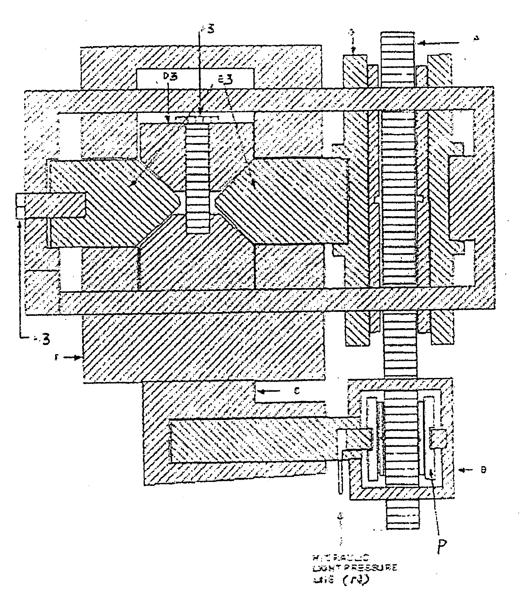
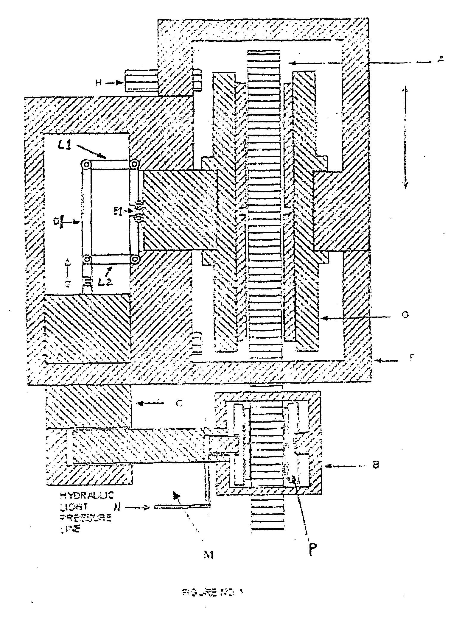
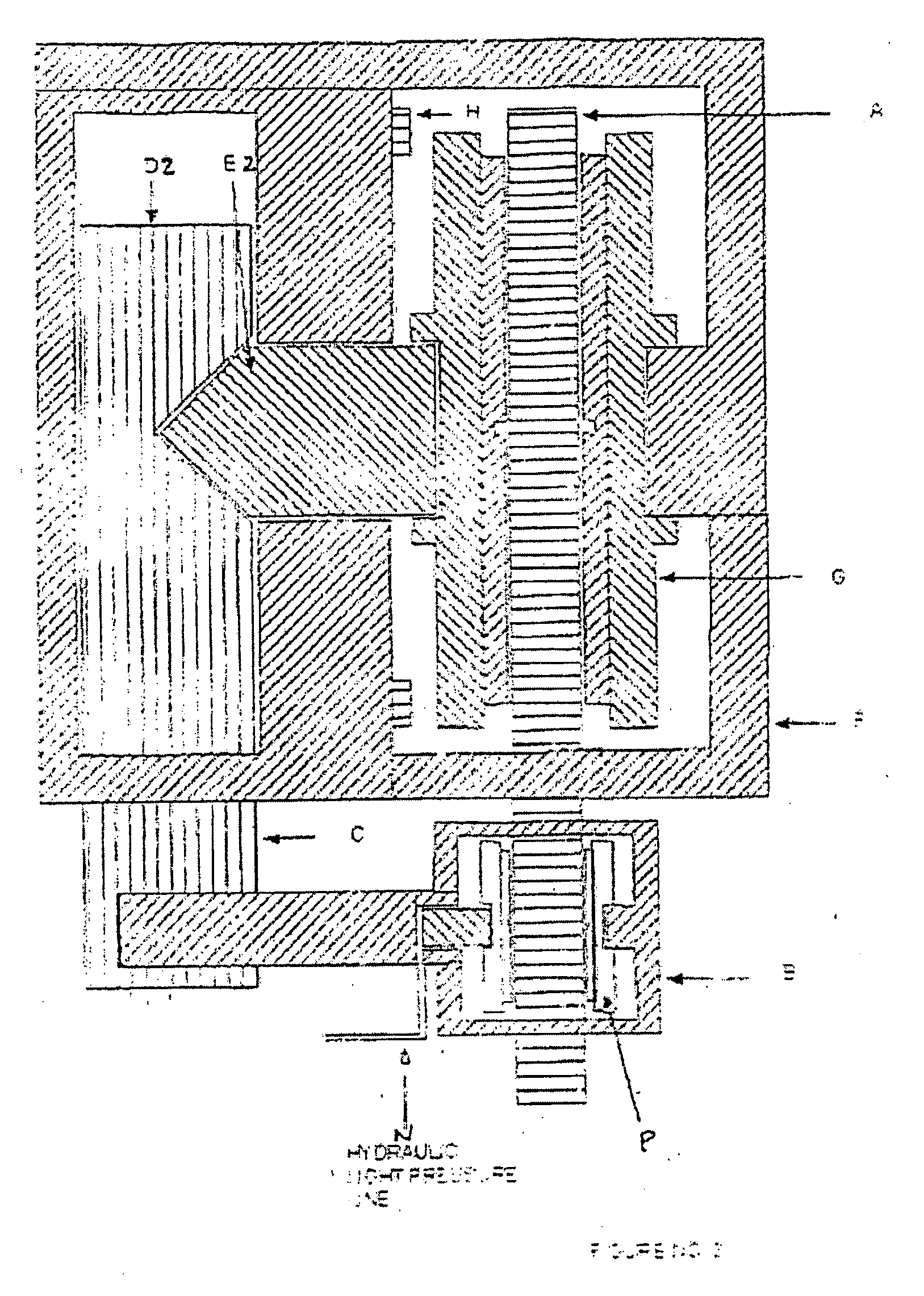
[0034]Referring to the drawings Self Activated Power Brake is made up of a rotating disk / drum (A) coaxially fitted to a wheel (not shown in figures). A housing (F) to hold brake shoes (G) of a brake is provided in a fixed position with respect to said rotating disk. A brake pedal system connected to hydraulic light pressure line (N) to transmit motion generated by hand or feet to at least one actuating pilot caliper (B). Said pilot caliper (B) is attached to preferably one actuating mechanism, which actuates said brake shoes (G). The actuating, mechanism has preferably one linkage mechanism (M) to link said pilot caliper to at least one transmitting means, so that force from the pilot caliper can be transmitted to said transmitting means. Said transmitting means applies force on at least one engaging means, when force is transmitted. Said engaging means, engages said brake shoes (G) to said rotating disk (A) when force is applied. The pilot caliper (B) is made up of at least one eng...


PUM


Abstract

A Self Activated Power Brake comprising a rotating brake disk fitted coaxially to a wheel and the main brake caliper/shoes fitted on dead axle/body frame. A sliding mechanism having shaped resembles to arc in orbit of brake disk. The mechanism having in two major parts, one is sliding and other is fixed which consists sliding bed and fitted with main power brake caliper. A pilot brake caliper, which is in sliding mode (floating mode), fitted on sliding part of the said sliding mechanism. At least one power transmitting means out of suggested means is needed to be linked the sliding pilot brake caliper to main power brake caliper to transfer the friction power of the pilot brake caliper after required amplification of the same. On braking action, the pilot brake caliper which is actuated by fluid line coming from master cylinder, actuates main power brake caliper through at least one power transmitting means as aforesaid to do the job as a SELF-ACTIVATED POWER BRAKE.

Description

FIELD OF THE INVENTION[0001]This invention relates to “Self Activated Power Brake”.BACKGROUND OF THE INVENTION[0002]The existing power brakes in automobiles, industries, railways etc. are activated by externally generated power through electric motor, hydraulic pump, air compressor or some other means. The power brake system is needed to assist or ease the driver of the vehicle or operator of the machine, as it requires a lot of power to stop any heavy moving object. This existing facility increases cost like the cost of electric motor, hydraulic pump or air compressor and running cost of the system too. In every braking system in a machine external force is required to stop or slow down the rotating wheel or any part of the machine, making the system as a whole more complicated and bulky.OBJECT OF THE INVENTION[0003]Object of this invention is to obviate the above drawbacks by providing a “Self Activated Power Brake”.SUMMARY OF THE INVENTION[0004]To achieve the said objective, this...

Claims


Application Information

Patent Timeline
Patent Type & Authority Applications(United States)
IPC IPC(8): B61H11/04
CPCB60T13/02F16D65/18F16D65/22F16D2127/12F16D2125/30F16D2125/66F16D2127/085F16D2121/02
Inventor TIWARI, ASHOK KUMARTIWARI, PADAM KUMAR
Owner TIWARI ASHOK KUMAR
Why Eureka
Try Eureka