Drive roll for a wire feeder

a technology of wire feeder and drive roll, which is applied in the field of drive roll, can solve the problems of poor quality welds or bird nesting, poor wire advancement accuracy, and wear of the drive roll, and achieve the effects of reducing the wear of the components

Active Publication Date: 2009-11-12
ILLINOIS TOOL WORKS INC
View PDF9 Cites 25 Cited by
  • Summary
  • Abstract
  • Description
  • Claims
  • Application Information

AI Technical Summary

Benefits of technology

[0012]The present invention overcomes the aforementioned challenges by providing a drive roll having an engagement ratio that accurately engages and advances the wire over a longer period of use, while imposing minimal wear on the components of the wire feeder. Furthermore, the engagement ratio allows the drive roll to better absorb the cyclical stresses, to maintain an advancement edge, and to minimize the deformation of the filler wire as it is driven between adjacent drive rolls.

Problems solved by technology

The cyclical engagement between the teeth, exacerbated by the stresses imparted by the clamping force, result in drive roll wear.
As the drive roll wears, the accuracy of the wire advancement is diminished and can ultimately lead to weak, poor-quality welds or bird-nesting (i.e., the wire becomes tangled in the drive rolls and related mechanisms).
Several techniques have been suggested to increase the useful life of the drive rolls, albeit with limited success.
While this technique may increase the useful life of a drive roll, the teeth continue to wear and the additional manufacturing operations are costly.
This increased force results in greater wear on other components of the wire feeder, such as the drive roller bearings.
Additionally, as with the fully knurled design, excessive deformation of the filler wire can result in poor quality welds.

Method used


Image

  • Drive roll for a wire feeder
  • Drive roll for a wire feeder
  • Drive roll for a wire feeder

Examples


Embodiment Construction

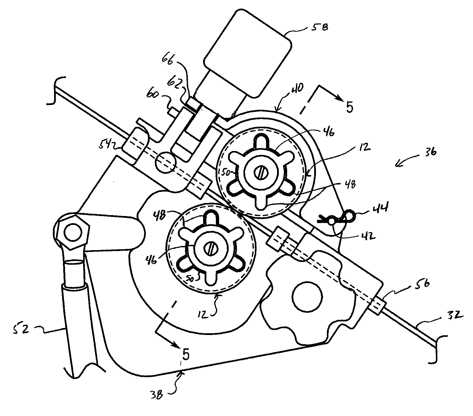
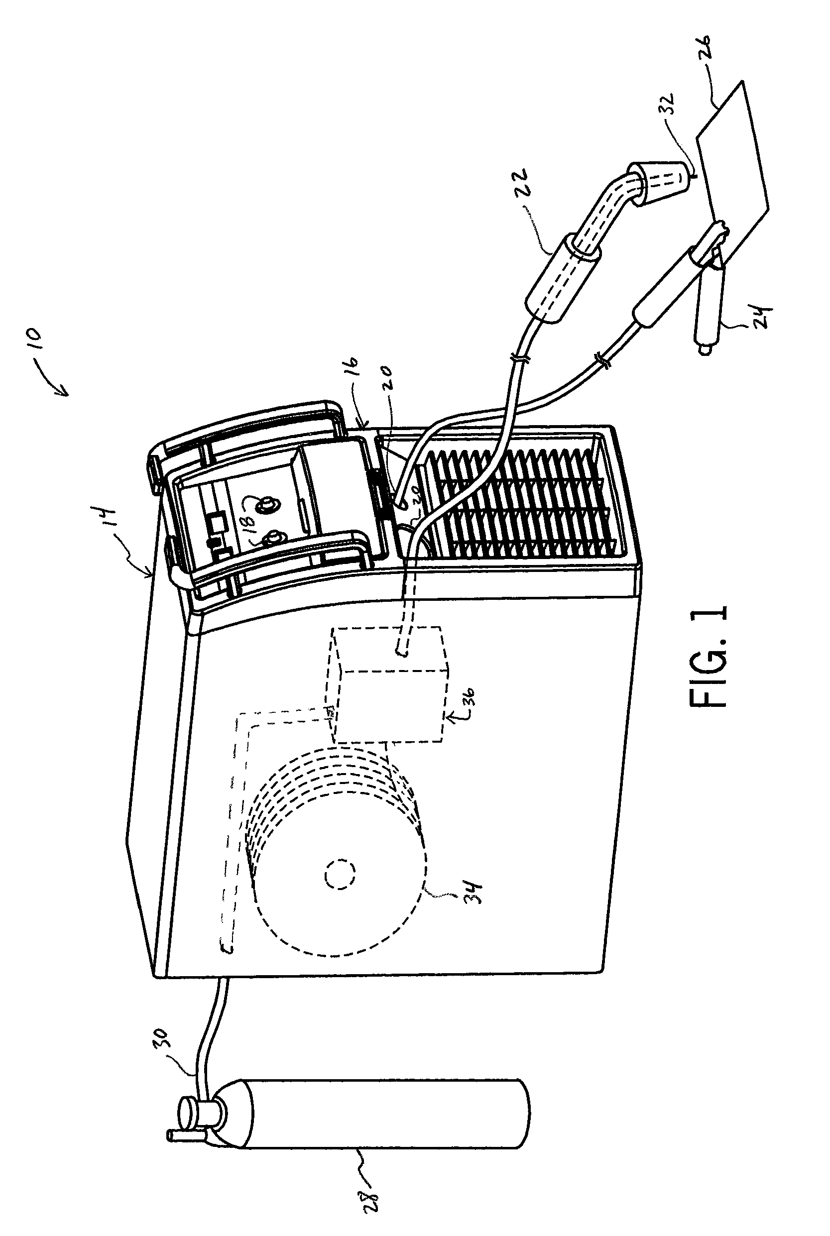
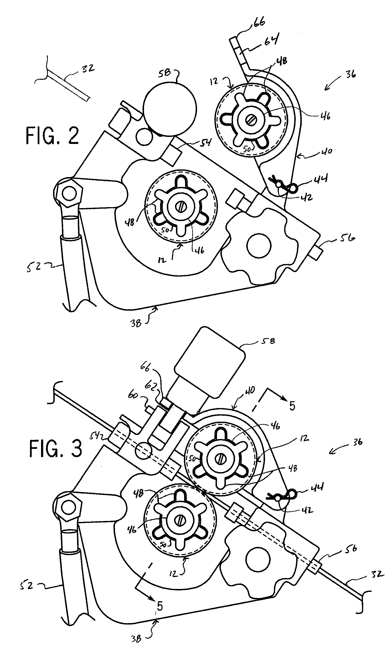
[0027]The present invention is described in relation to a gas metal arc welding (“GMAW”) system including a wire feeder having opposing drive rolls. However, the many aspects of the present invention are equally applicable to various other types of systems that require some form of drive roll to manipulate a driven object, such as a pipe roller. Moreover, numerous configurations of single or multiple drive rolls are contemplated by the present invention. For example, while a pair of opposing drive rolls are described, two pairs of opposing drive rolls may be configured or a three-to-two configuration may be used where the weight of the driven object requires additional support (i.e., three drive rolls beneath the object and two above). Furthermore, multiple drive rolls may be used where the driven object is highly sensitive to surface pressure, as the use of multiple drive rolls in accordance with the present invention will help disperse the overall forces applied to the object.

[002...


PUM

PropertyMeasurementUnit
areaaaaaaaaaaa
angleaaaaaaaaaa
electricalaaaaaaaaaa

Abstract

A drive roll is disclosed that is useable in a wire feeder for advancing a wire. The drive roll includes a first side, a second side offset from the first side, and an annular surface between the first side and the second side. An annular groove is formed in the annular surface and defines an engagement surface. Pluralities of lands are spaced along the engagement surface and pluralities of notches are formed in the engagement surface for engaging and advancing the wire. An engagement ratio is defined between the total land area of the plurality of lands and the total notch area of the plurality of notches calculated at the engagement surface. The engagement ratio defines a drive roll that accurately engages and advances the wire over a longer period of use.

Description

REFERENCE TO RELATED APPLICATIONS[0001]Not applicable.STATEMENT REGARDING FEDERALLY SPONSORED RESEARCH OR DEVELOPMENT[0002]Not applicable.BACKGROUND OF THE INVENTION[0003]The present invention relates generally to drive rolls for use in welding-type wire feeders and, more particularly, to a drive roll with an improved engagement configuration.[0004]Certain welding techniques, such as gas metal arc welding (“GMAW”) incorporate a consumable wire electrode. During the welding process, a metal wire is fed through a welding-type gun where the wire ultimately conducts electrical current and serves as a filler metal forming the weld.[0005]A mechanism, commonly known as a wire feeder, is used to advance the wire from a spool to the welding-type gun during the welding process. The wire feeder typically includes two opposing drive rolls. Each drive roll is rotatably mounted such that the wire is fed between the periphery of each complementary rotating drive roll at a pinch zone. The clamping ...

Claims


Application Information

Patent Timeline
Patent Type & Authority Applications(United States)
IPC IPC(8): B23K9/12B23B3/00
CPCB23B27/24Y10T82/10B23K9/1336
Inventor LEITERITZ, NATHAN
Owner ILLINOIS TOOL WORKS INC
Why Eureka
Try Eureka