
A method of treating an electrically insulating oil

Inactive Publication Date: 2009-11-12
ABB RES LTD
View PDF5 Cites 2 Cited by
  • Summary
  • Abstract
  • Description
  • Claims
  • Application Information

AI Technical Summary

Benefits of technology

[0011]One embodiment of the present invention is to provide a method and apparatus by means of which an electrically insulating oil used as insulation in an electrical apparatus may be treated in order to remove reactive organic sulphur compounds and thereby prevent the formation of copper sulphide therein.

Problems solved by technology

The process is complex, time consuming and the columns with scavenger and sorbent have to be regenerated after some processing time.

Method used


Image

  • A method of treating an electrically insulating oil
  • A method of treating an electrically insulating oil
  • A method of treating an electrically insulating oil

Examples


Embodiment Construction

[0043]Detailed descriptions of the preferred embodiment are provided herein. It is to be understood, however, that the present invention may be embodied in various forms. Therefore, specific details disclosed herein are not to be interpreted as limiting, but rather as a basis for the claims and as a representative basis for teaching one skilled in the art to employ the present invention in virtually any appropriately detailed system, structure or manner.

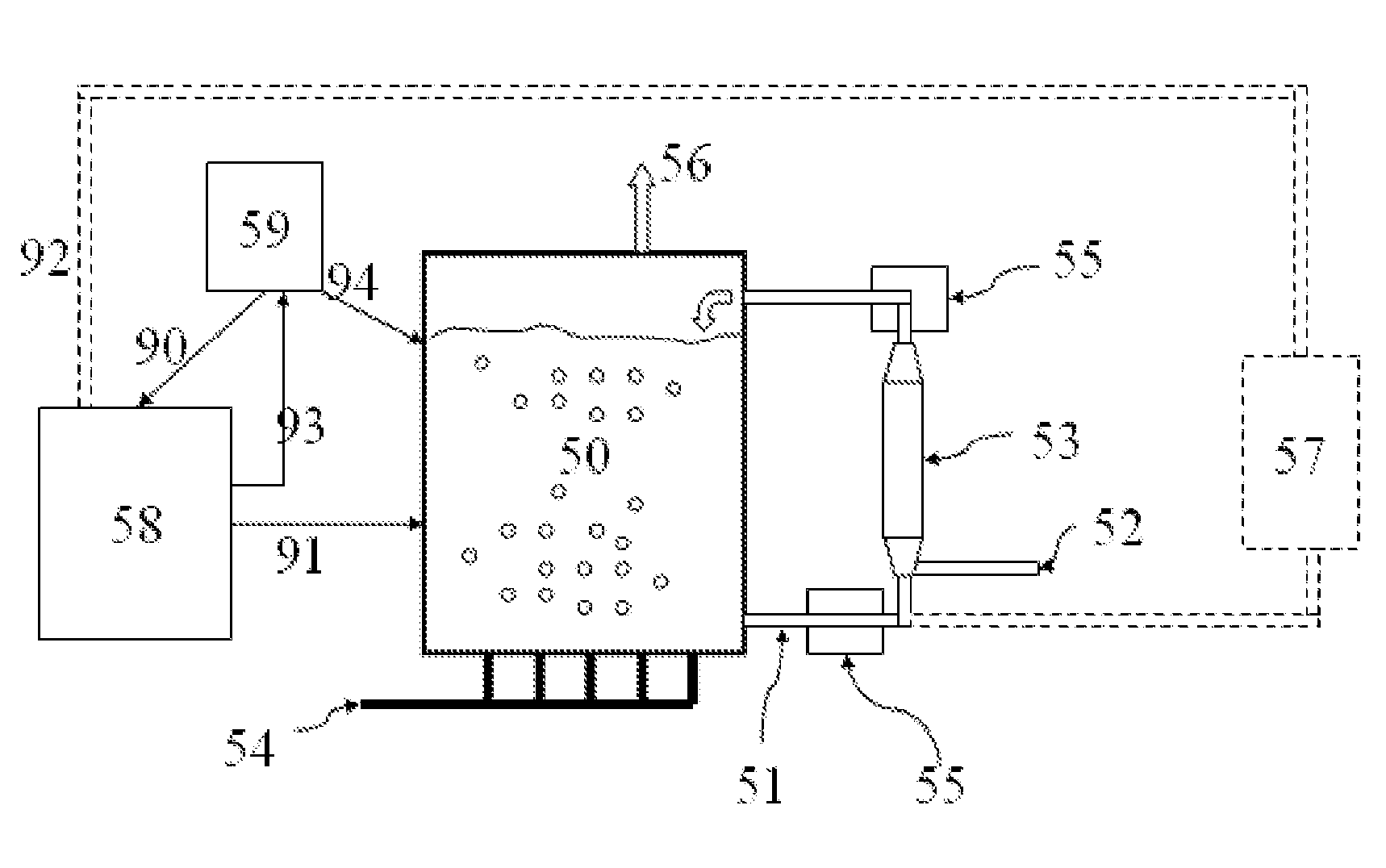
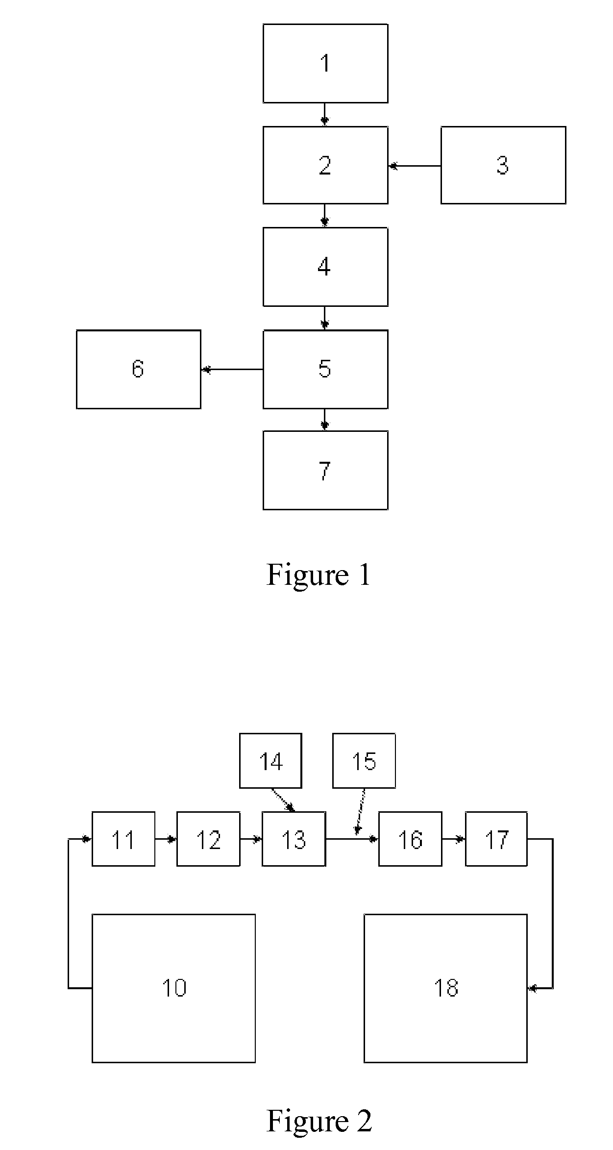
[0044]FIG. 1 shows a schematic process diagram of the method. In block 1 the electrically insulating oil is tempered to the correct temperature for the reaction to proceed. In block 2 the chemical agent (from the chemical agent source in block 3) is added to the oil together with an inert gas and starts to react with the reactive organic sulphur compound present in the oil. The inert gas is added to the oil to assist the reaction between the chemical agent and the reactive organic sulphur compound, by allowing volatile reaction produ...


PUM


Abstract

A method of treating an electrically insulating oil, wherein the oil includes at least one reactive organic sulphur compound. A chemical agent causing a reaction with the reactive organic sulphur compound is added to the oil. The chemical agent includes an elementary halogen or a halogen compound.

Description

TECHNICAL AREA[0001]The present invention relates to a method of treating an electrically insulating oil, wherein the oil comprises at least one reactive organic sulphur compound.TECHNICAL BACKGROUND[0002]Insulating oils are used in a number of different apparatus in the field of electrical power transmission and electrical power generation, for example; power transformers, distribution transformers, tap changers, switchgear and reactors.[0003]These electrically insulating oils often contain traces of reactive organic sulphur compounds, for example organic disulphides or thiols (also known as mercaptans), and these reactive sulphur compounds may react with copper or copper oxide, forming copper sulphide (Cu2S).[0004]One possible reaction path is by copper reacting with thiols forming copper mercaptides. The copper mercaptides can decompose further, leading to the formation of copper (I) sulphide, Cu2S.Cu2O+2RSH=>2CuSR+H2O2CuSR=>Cu2S+RSRwhere RSH is a thiol, —SH is a thiol grou...

Claims


Application Information

Patent Timeline
IPC IPC(8): H01B3/20H01B3/24B01J19/00G01N21/00
CPCC10M175/0016C10N2240/201C10M2219/08C10N2040/16
Inventor GUSTAFSSON, KARINLEANDERSSON, ROBERT
Owner ABB RES LTD
Learn More