Radio-frequency surface coils comprising on-board digital receiver circuit

a digital receiver and surface coil technology, applied in the field of magnetic resonance imaging and spectroscopy, can solve problems such as complex and expensive systems, and achieve the effect of simplifying mn imaging and reducing both complexity and cos

Inactive Publication Date: 2009-11-12
KONINKLIJKE PHILIPS ELECTRONICS NV
View PDF10 Cites 20 Cited by
  • Summary
  • Abstract
  • Description
  • Claims
  • Application Information

AI Technical Summary

Benefits of technology

[0003]Accordingly, an RF coil system that simplifies MN imaging is disclosed herein, the RF coil system comprising a transmitter coil for transmitting an RF signal to excite a target region, and a planar receiver coil assembly for receiving an MR signal from at least a portion of the target region, wherein the planar receiver coil assembly includes an on-board digital receiver circuit for processing the received magnetic resonance signal. A single transm

Problems solved by technology

However, using their RF array coil to perform multi-nuclear (MN) imaging could result in a complicated and expensive system, as much of the hardware will need to

Method used


Image

  • Radio-frequency surface coils comprising on-board digital receiver circuit
  • Radio-frequency surface coils comprising on-board digital receiver circuit
  • Radio-frequency surface coils comprising on-board digital receiver circuit

Examples


Embodiment Construction

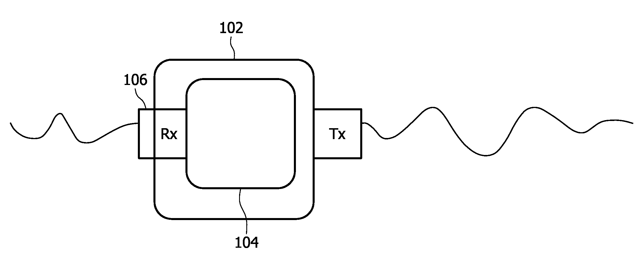
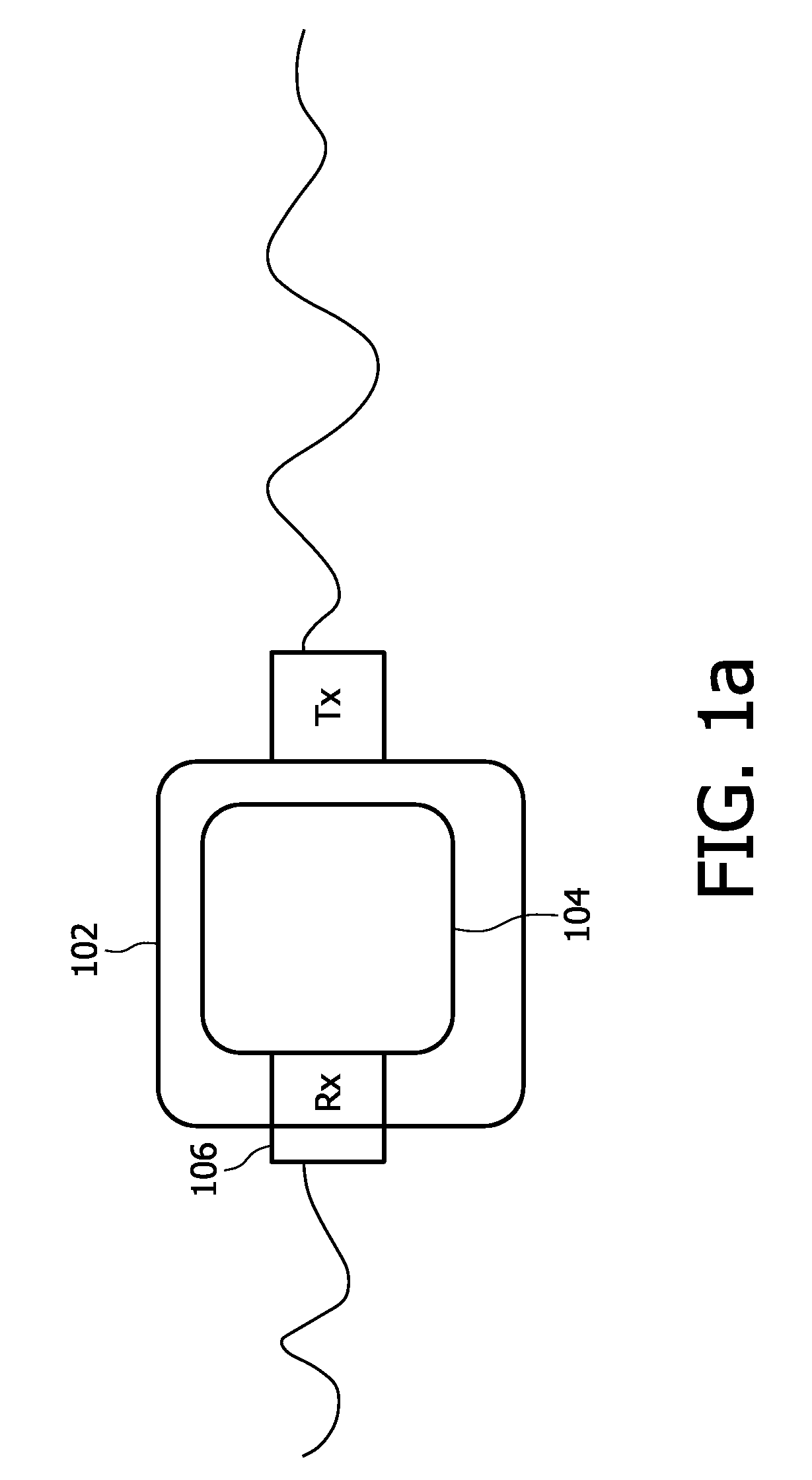
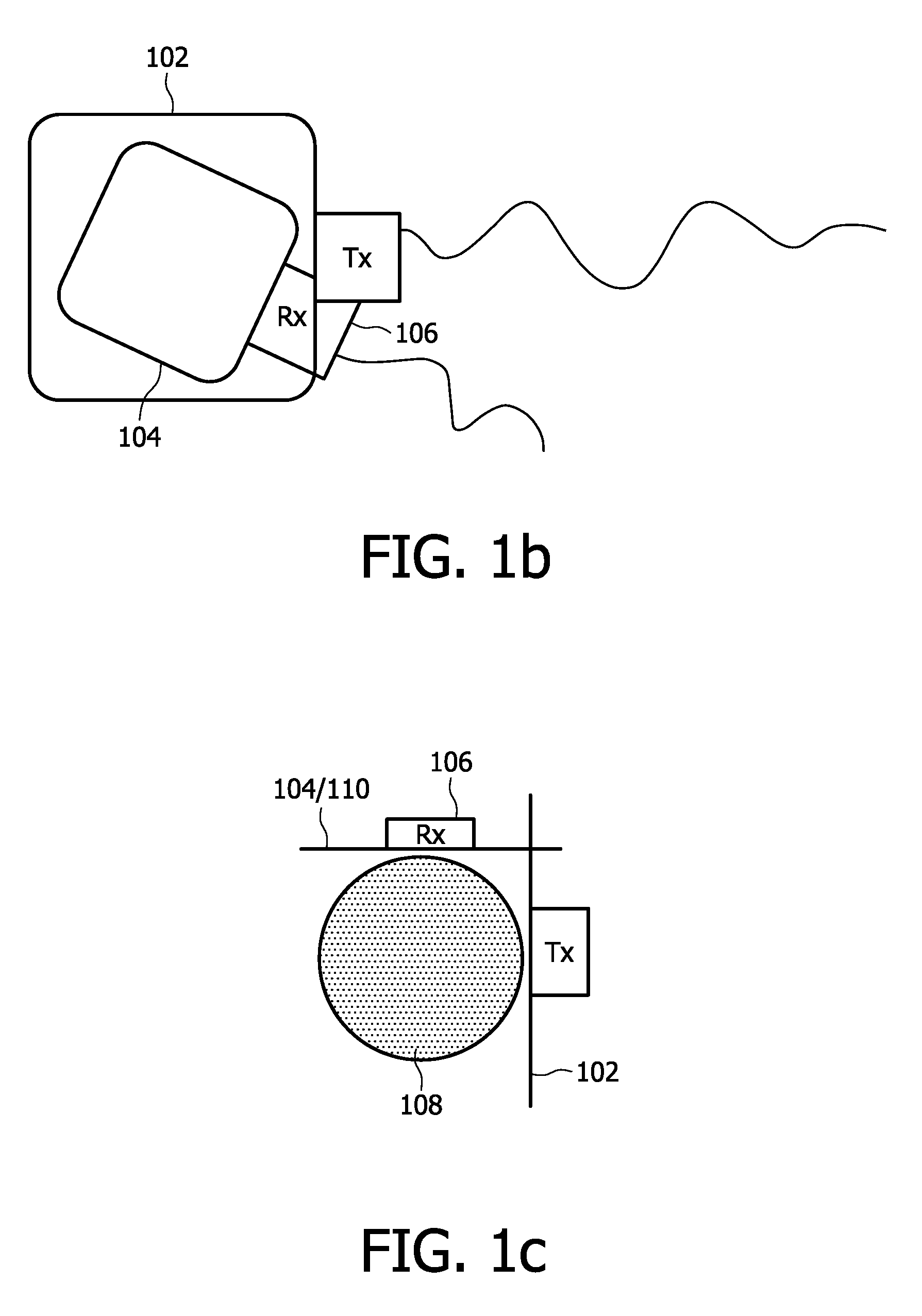
[0015]FIG. 1a-1e show various embodiments of an RF coil system comprising a transmitter coil 102 and one or more planar receiver coil assemblies 104, 110. Each planar receiver coil assembly 104, 110 includes an on-board digital receiver circuit 106, 112 capable of processing MR signals received by the respective planar receiver coil assembly 104, 110. In some embodiments the planar receiver coil assembly 104, 110 is configured to overlap the transmitter coil 102 (FIG. 1a, 1b, 1d, 1e), while in other embodiments the transmitter coil 102 and the planar receiver coil assembly 104, 110 are placed orthogonal to each other (FIG. 1c). In either the parallel or the orthogonal configuration, the planar receiver coil assembly 104, 110 is arranged to receive MR signal, for example, free induction decays or echoes, from at least a part of a region that has been excited by the transmitter coil 102.

[0016]The transmitter coil 102 and the planar receiver coil assembly 104, 110 are electrically inde...


PUM


Abstract

A radio-frequency (RF) coil system that simplifies multi-nuclear magnetic resonance (MR) imaging is disclosed herein. The RF coil system comprises a transmitter coil (102) for transmitting an RF signal to excite a target region of a subject. The RF coil system also comprises an independent planar receiver coil assembly (110) for receiving an MR signal from at least a portion of the target region, the planar receiver coil assembly (110) being configured to include an on-board digital receiver circuit (112) for processing the received MR signal.

Description

FIELD OF THE INVENTION[0001]This invention relates to magnetic resonance (MR) imaging and spectroscopy, and particularly to radio-frequency (RF) coils.BACKGROUND OF THE INVENTION[0002]U.S. Pat. No. 6,946,840 discusses an RF array coil comprising a plurality of transmitter and receiver coils. However, using their RF array coil to perform multi-nuclear (MN) imaging could result in a complicated and expensive system, as much of the hardware will need to be duplicated to enable the transmitter to excite different nuclear species, as well as to enable the receiver to receive data from each different nuclear species. It is therefore desirable to have a simpler and cheaper implementation of an RF coil system that is capable of MN imaging. It is also desirable to have a simpler and cheaper method of MN imaging using the said RF coil system, as well as to have an MR system capable of performing MN imaging in a simpler and cheaper fashion utilizing the said RF coil system.SUMMARY OF THE INVEN...

Claims


Application Information

Patent Timeline
IPC IPC(8): G01R33/48G01R33/44
CPCG01R33/288G01R33/341G01R33/3621G01R33/3692G01R33/3642G01R33/3657G01R33/3635
Inventor HARVEY, PAUL ROYSTON
Owner KONINKLIJKE PHILIPS ELECTRONICS NV
Why Eureka
Try Eureka