Method and apparatus for robust super-resolution video scaling

a super-resolution, video scaling technology, applied in the field of video image processing, can solve the problems of high-visibility artifacts, unstable motion compensation techniques, and introduction of visible artifacts

Inactive Publication Date: 2009-11-12
ZORAN CORPORATION
View PDF11 Cites 18 Cited by
  • Summary
  • Abstract
  • Description
  • Claims
  • Application Information

AI Technical Summary

Benefits of technology

[0016]The method according to the invention can further comprise a penalization of the insensitive loss by a total variation increment. This penalization provides a control over the oscillations introduced by the selected best interpolation. For each parameterized interpolator and for each new point the method can include the computation of a total variation increment resulting from an aggregation of input image values and interpolated values calculated by the parameterized interpolator, in a one-dimensional neighborhood of the new point. This one-dimensional neighborhood can be chosen to be horizontal or vertical. For each parameterized interpolator this total variation increment is filtered spatially with a weighted sum in a spatial neighborhood of each new point and this regularized total variation increment is provided in input of the minimum loss selection process. For each new point, the regularized insensitive loss can be penalized by the regularized total variation increment at said new point so that the selected best parameterized directional interpolation minimizes this penalized regularized insensitive loss among all parameterized interpolations at the new point.

Problems solved by technology

When the input image is interlaced, it is sampled much below the Shannon sampling rate, and interpolations thus produce artifacts that are highly visible in the resulting video.
Directional interpolations can partly reduce these artifacts but not completely because the information necessary to perform the interpolation is not available.
In presence of significant motion, these techniques implement a spatial interpolations and thus produce the same type of artifacts as spatial interpolation techniques.
Yet, existing motion compensated techniques are unstable and introduce visible artifacts.
Indeed, computing precisely the displacement of image pixels is difficult, specially with interlaced images that are undersampled.
Motion discontinuities at occlusions or fine scale motions such as produced by dust, or motion transparencies produce motion estimation errors that yield artifacts when using these motion vectors for time interpolation.
None of the state of the art procedures for video scaling fully takes fully advantage of the space-time information provided by an input-video sequence in order to perform a super-resolution scaling of high quality.

Method used


Image

  • Method and apparatus for robust super-resolution video scaling
  • Method and apparatus for robust super-resolution video scaling
  • Method and apparatus for robust super-resolution video scaling

Examples


Embodiment Construction

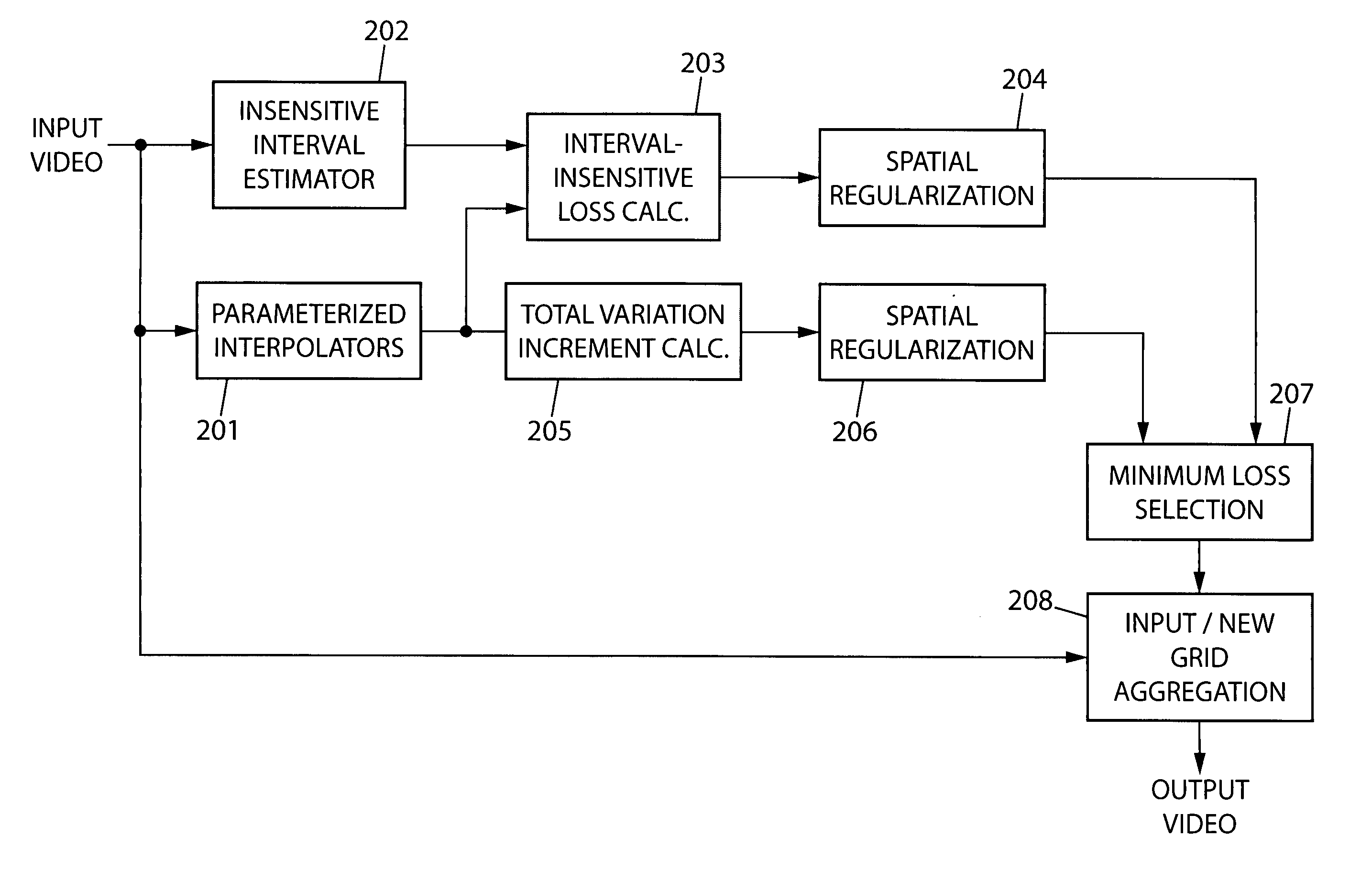
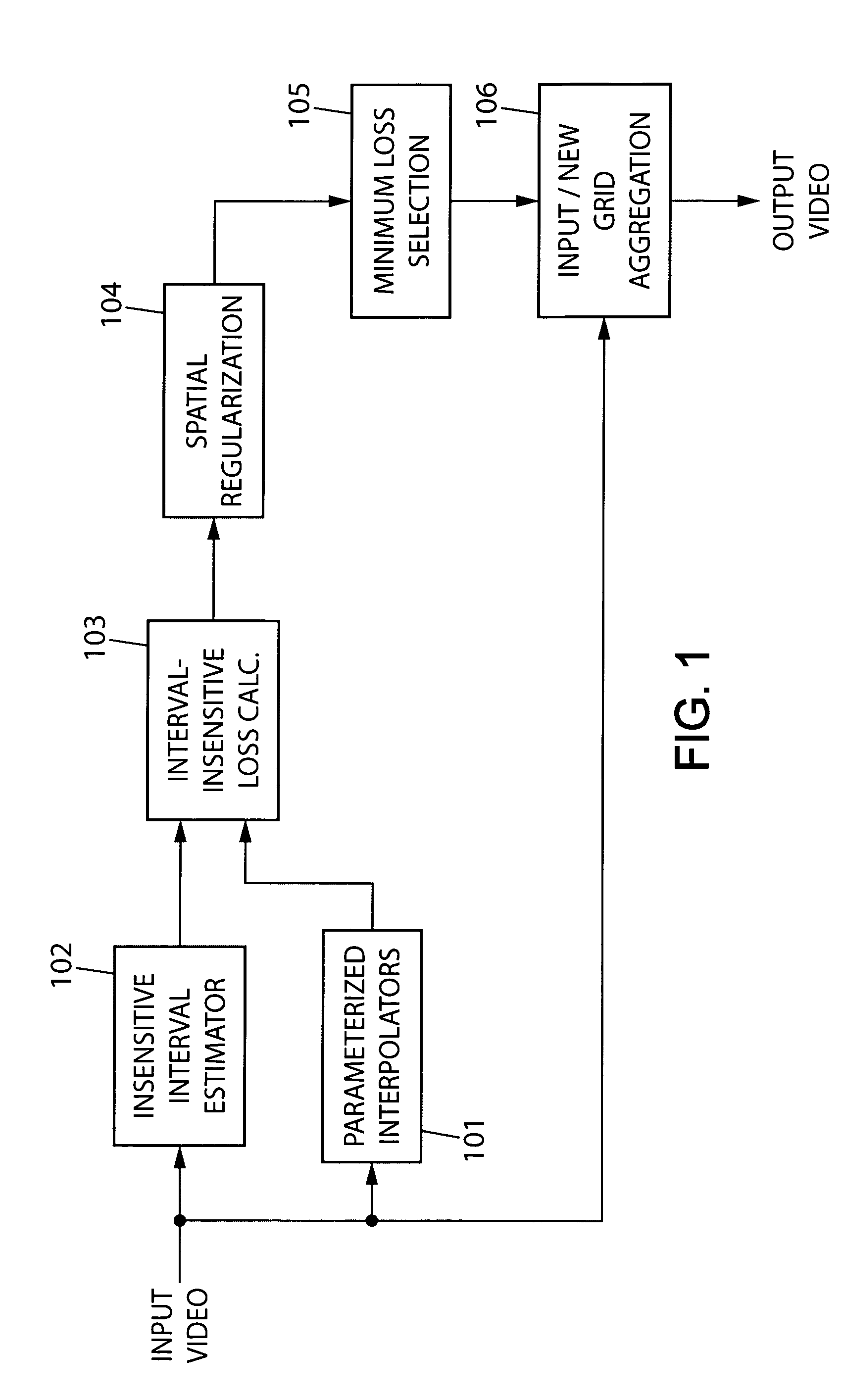
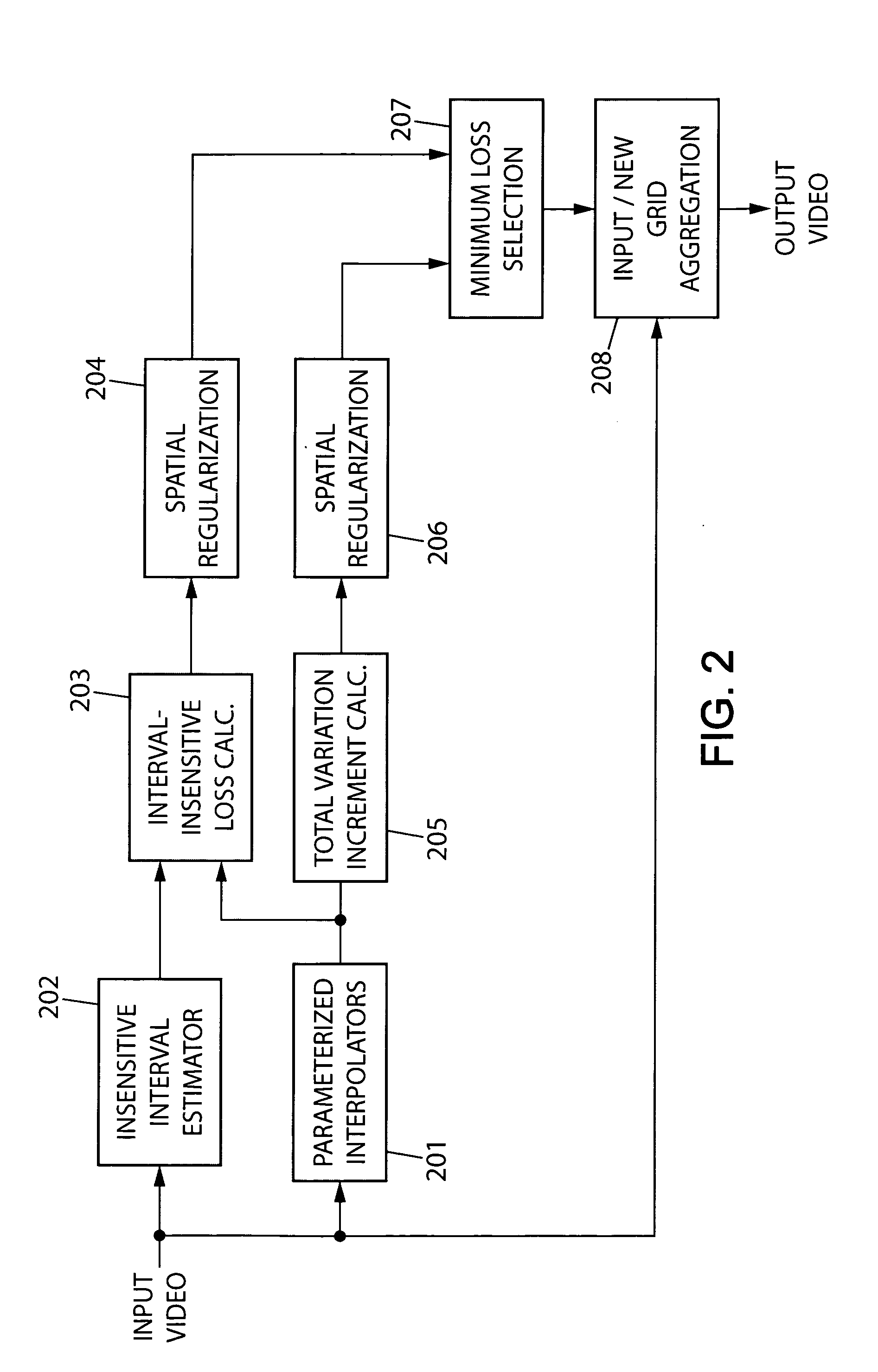
[0032]FIG. 1 shows a first apparatus exemplifying the present invention. The apparatus processes a video signal of 2D images defined on a spatio-temporal input grid G. For each time index t, where t is an integer parameter, the spatio-temporal input-grid G is a grid of points whose coordinates in R3 are x(n1, n2, t)=n1τ1+αn2τ2+τ3+τ4(t) where τ1=(1, 0, 0) and τ2=(0, 1, 0) are normalized horizontal and vertical spatial vectors, τ3=(0, 0, 1) is a vector along time, and τ4(t) is a spatial shift that depends if the video is interlaced or progressive. If the input video is interlaced then it is composed of two fields at two time instant t and t+1, where for t even the first one includes the even rows and the second one the odd row. In this case the input grid are defined in R3 by α=2 and τ4(t)=(0, 0, 0) if t is even and τ4(t)=(0, 1, 0) if t is odd. If the input video is progressive then α=1 and τ4(t)=(0, 0, 0) for all t. To each input grid point x(n1, n2, t) the input video gives an image...


PUM


Abstract

A method and apparatus for scaling video images, which applies more particularly to techniques for converting video sequence formats and deinterlacing. The invention comprises a parameterized interpolation (101) which computes interpolations at each new point of the output. An insensitive interval estimation (102) computes an interval where the probability distribution of the output image value is estimated to have its maximum, and an insensitive loss calculation (103) derives for each interpolation value a negative log likelihood measurement from an interval-insensitive probability distribution. After a spatial regularization (104) the invention includes a minimum loss selection (105) which selects the minimum loss interpolation at each new point and provides it as an output image value. The invention also includes a total variation increment module and a directional matching error module that can penalize the insensitive loss, for the minimum loss selection.

Description

BACKGROUND OF INVENTION[0001]The present invention relates generally to the processing of video images and more particularly to techniques for converting video sequence formats with scaling. The multiplicity of video formats requires to adapt the format of an incoming video to the format required by a display device or for transmission. In an interlaced video, each successive image, also called field, provide alternatively in time even and odd lines. Simple Definition television (SDTV) such as NTSC, PAL and SECAM television format, are interlaced. An interlaced monitor such as a cathode ray tube (CRT) is designed to display these fields, with an interlaced scanning of even and odd lines. Progressive video image formats incorporate all lines (even and odd) in each image. LCD video monitors are designed to display progressive videos. For an input interlaced video it is thus necessary to perform a deinterlacing that compute respectively the missing odd and even lines in each field of t...

Claims


Application Information

Patent Timeline
Patent Type & Authority Applications(United States)
IPC IPC(8): H04N7/01
CPCG06T3/4007
Inventor BRUNA, JOANMALLAT, STEPHANE
Owner ZORAN CORPORATION
Why Eureka
Try Eureka