
Heat dissipation device of notebook computer

a notebook computer and heat dissipation device technology, applied in the direction of lighting, heating apparatus, electric apparatus casings/cabinets/drawers, etc., can solve the problems of reducing the heat dissipation efficiency, increasing the cost, and unable to effectively remove heat from the pegs, so as to improve the heat dissipation effect, reduce manufacturing costs, and increase the heat dissipation surface area

Inactive Publication Date: 2009-11-12
HSIN I TECH CO LTD
View PDF7 Cites 14 Cited by
  • Summary
  • Abstract
  • Description
  • Claims
  • Application Information

AI Technical Summary

Benefits of technology

[0010]An objective of the present invention is to provide a heat dissipation device for a notebook computer in order to enhance heat dissipation result and reduce the manufacturing costs.
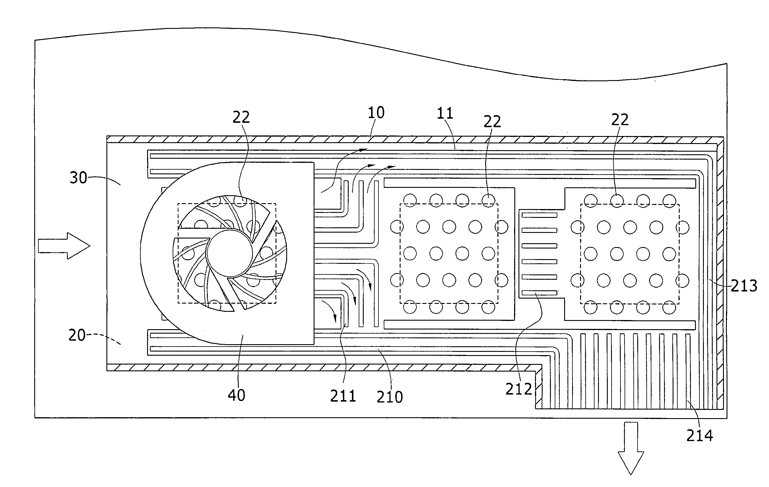
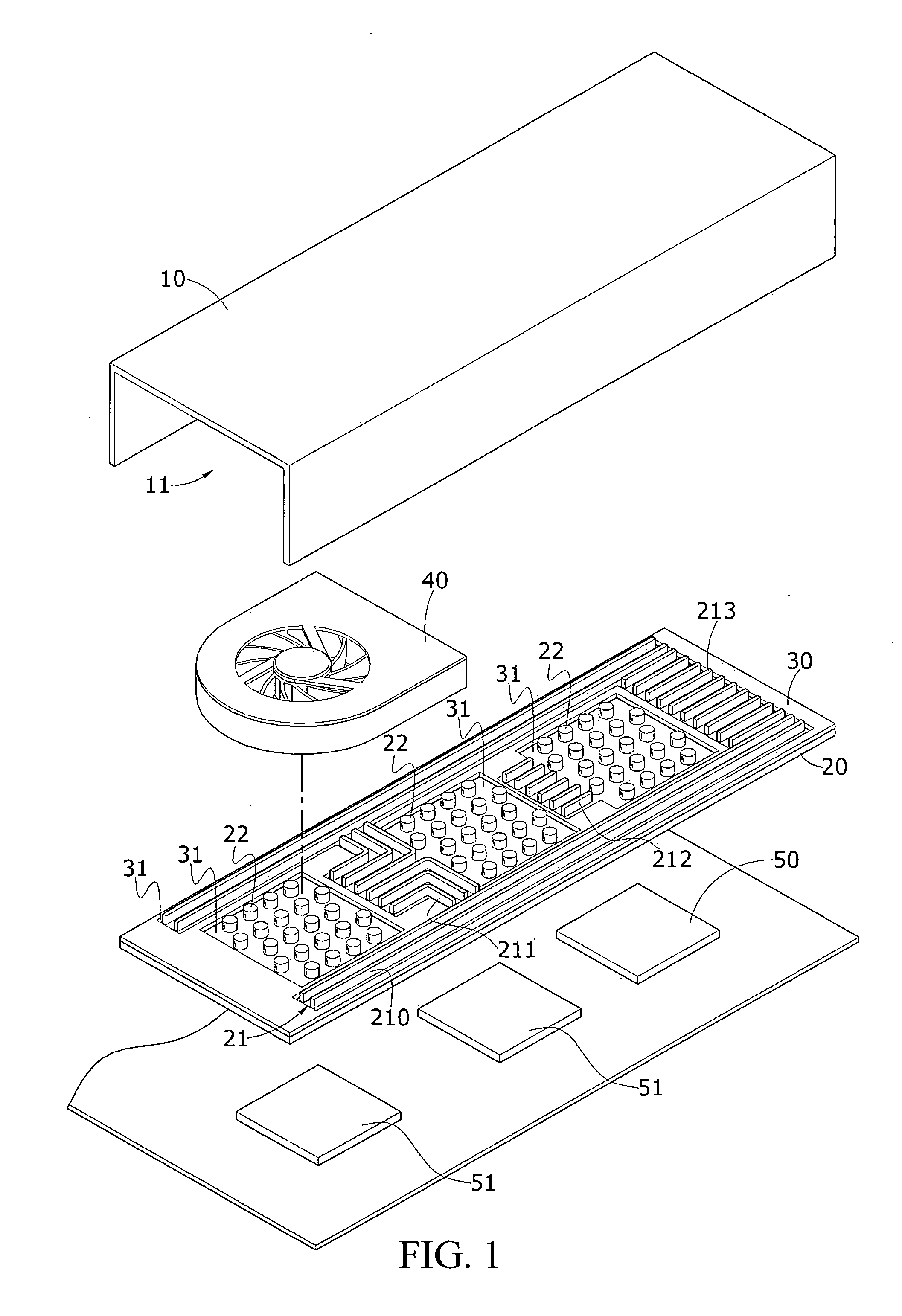
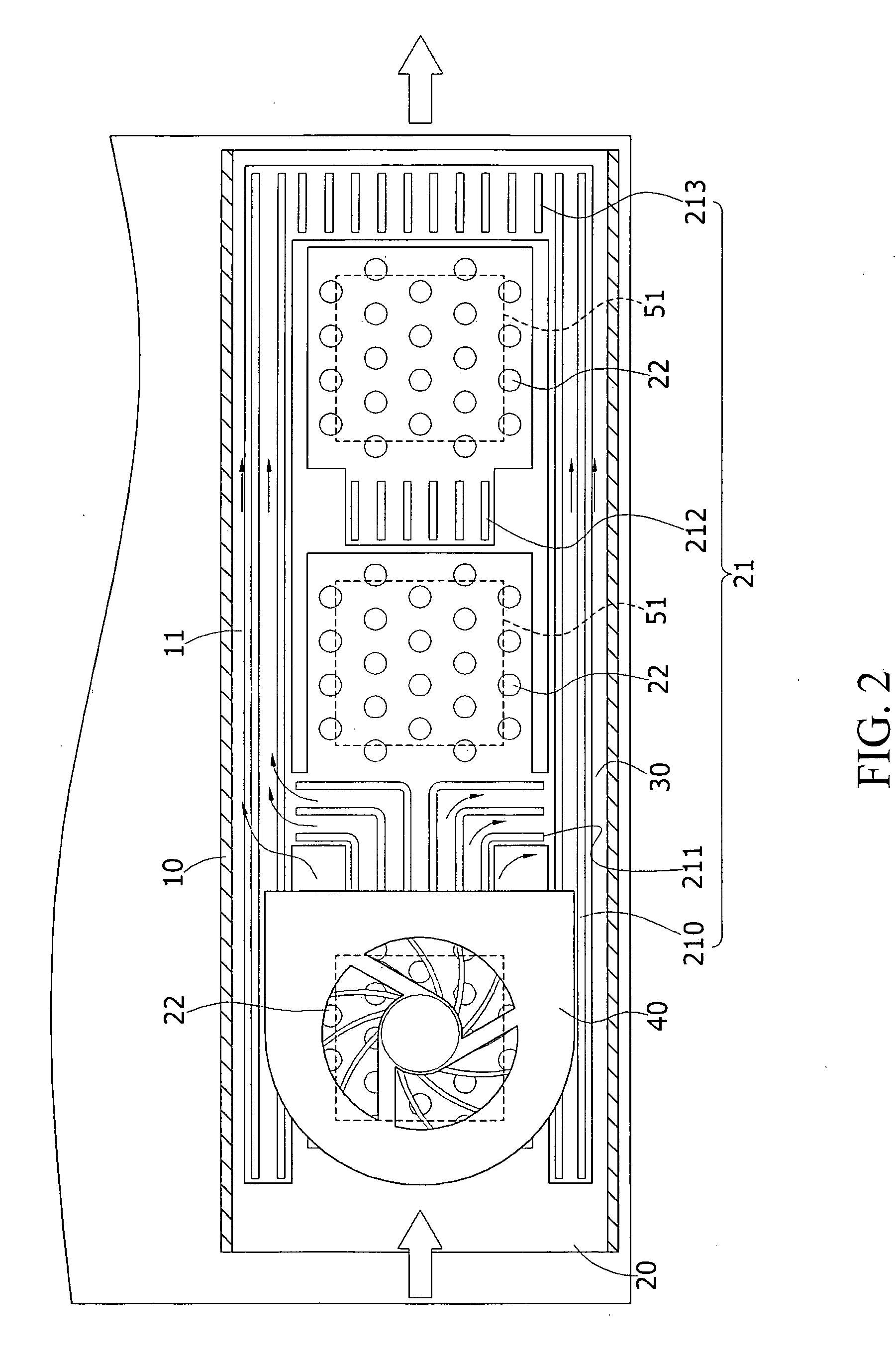
[0011]As compared to the known techniques, the present invention combines a hood and a bottom board to form a heat dissipation channel. The bottom board forms a plurality of fins and pegs to increase the heat dissipation surface area. The bottom board is provided with at least one fan to sequentially and smoothly expel heat generated by heat sources through the heat dissipation channel in order to replace the conventional copper-made heat conducting pipes. Thus, the present invention can realize efficient heat dissipation and reduction of costs.

Problems solved by technology

(1) The known techniques use a plurality of copper-made solid heat conducting pipes to serve as a heat dissipation structure, which increases the costs.
(2) Using the copper-made solid heat conducting pipes to transfer heat cannot provide an efficient conduct of heat, leading to decreased efficiency of heat dissipation.
(3) The copper-made heat conducting pipe, which is solid, may easily accumulate heat therein and is incapable to properly expel the heat, so that the solid, copper-made heat conducting pipe is maintained in high temperature for a long term, making it impossible to effectively remove heat from the pegs.
(4) The known copper-made heat conducting pipe has to work with a fan disposed next thereto so that it can only be configured as an L-shape, which occupies a large amount of installation space.

Method used


Image

  • Heat dissipation device of notebook computer
  • Heat dissipation device of notebook computer
  • Heat dissipation device of notebook computer

Examples


Embodiment Construction

[0019]With reference to FIGS. 1-3, a heat dissipation device constructed in accordance with an embodiment of the present invention, which is applied to heat sources inside a notebook computer, comprises a hood 10, a bottom board 20 opposite to the hood 10, a thermal insulation layer 30 mounted atop the bottom board 20, and at least one fan 40. It is noted that the present invention is described with reference to a heat source such as a chipset to demonstrate heat dissipation therefrom, but the present invention is not limited to such an application and can also be applied to remove heat from a random access memory or other heat sources for example.

[0020]The hood 10 forms a receiving space having a downward-facing opening and in the embodiment illustrated, the hood 10 is made an elongate hood, but is not limited thereto and can be of other configurations in other feasible applications.

[0021]The bottom board 20 is set opposite to and attached below the hood 10 and forms a heat dissipa...


PUM


Abstract

A heat dissipation device is provided for dissipating heat from a heat source inside a notebook computer, and includes a hood, a bottom board, a thermal insulation layer, and at least one fan. The hood and the bottom board together define a heat dissipation channel. The bottom board integrally forms a plurality of fins and pegs. The bottom board is set above the heat source. The fan is set above the bottom board to efficiently expel heat from the inside to the outside. With the plurality of fins and pegs, the heat dissipation surface area of the bottom board and the heat source is increased and the overall heat dissipation performance is enhanced.

Description

TECHNICAL FIELD OF THE INVENTION[0001]The present invention generally relates to a heat dissipation device of a notebook computer, and particularly to a heat dissipation device that is provided for a notebook computer and is arranged on a heat source of the notebook computer for enhancing heat dissipation.DESCRIPTION OF THE PRIOR ART[0002]With the development of electronic / information devices, notebook computers are getting popular nowadays. Due to the elevated requirement in respect of the operation speed, heat dissipation performance, and compactness of a notebook computer by the consumers, the heat dissipation performance of a notebook computer is now of vital importance. For regular notebook computers, one of the heat sources is a chipset. The notebook computer chipsets include a central processing unit (CPU), a northbridge chipset, and a southbridge chipset. Thus, effectively removing the heat generated by the above discussed heat sources in order to improve the heat dissipatio...

Claims


Application Information

Patent Timeline
Patent Type & Authority Applications(United States)
IPC IPC(8): H05K7/20G06F1/20
CPCG06F1/203
Inventor CHEN, CHIEN-YUANCHUANG, YING-TECHEN, YI-SHENG
Owner HSIN I TECH CO LTD
Learn More