Image forming apparatus

Inactive Publication Date: 2009-11-12
RICOH KK
View PDF10 Cites 13 Cited by
  • Summary
  • Abstract
  • Description
  • Claims
  • Application Information

AI Technical Summary

Problems solved by technology

However, a drawback to the use of the separation pawl is that, because the separation pawl contacts the fixing roller / belt, the separation pawl may easily scratch the surface of the fixing roller / belt, leaving a scratch mark or a trace thereon.
When this happens, the output image has undesirable markings such as streaks.
Accordingly, the product life of the fixing roller of this kind is relatively long.
A drawback of the foregoing configuration is that the surface layer is relatively soft and thus damaged or scratched easily.
However, a drawback of the contactless separation method is that it is susceptible to paper jams when the viscosity of the toner and of the fixing roller is relatively high, causing the recording sheet to roll around the fixing roller after fixation.
In particular, when a color image is formed, a plurality of color layers is overlaid on one another, increasing viscosity and thus causing paper jams more easily.
As a result, paper jams occur.
However, when the compressor is used, the size of the image forming apparatus as a whole increases.
In addition, compression of air takes time until a desired high-pressure air is obtained.
Consequently, the compressed air cannot be used immediately after the image forming apparatus is turned on.
Furthermore, a solenoid valve is required, thereby increasing the number of parts and thus significantly increasing the cost of the device.
Moreover, when the compressor is driven, causing significant noise, it is not suitable for office use.
Such an air supply mechanism tends to be large, consuming significant amount of power, thereby defeating the purpose of power saving.
Finally, the typical image forming apparatus using the compressor is a full-color high speed printing machine that tends to be large, expensive, and requiring a dedicated operator.
As with larger air supply devices, with a compact air supply device as well, when air ejection is either too early or too late, the recording sheet does not successfully separate from the fixing roller / belt, causing paper jams.
Although this configuration allows the recording sheet to separate reliably, the detector and a driver circuit are necessary, increasing cost as well as the size of the device.
Furthermore, paper dust or the like sticks to the surface of the detector after extended use, contaminating the detector and thus necessitating periodical maintenance.
In a case of ejecting air continuously as in the conventional air supply device, the product life is relatively short, and consumption of energy increases.

Method used


Image

  • Image forming apparatus
  • Image forming apparatus
  • Image forming apparatus

Examples


Embodiment Construction

[0054]In describing illustrative embodiments illustrated in the drawings, specific terminology is employed for the sake of clarity. However, the disclosure of this patent specification is not intended to be limited to the specific terminology so selected, and it is to be understood that each specific element includes all technical equivalents that operate in a similar manner and achieve a similar result.

[0055]Illustrative embodiments of the present invention are now described below with reference to the accompanying drawings.

[0056]In a later-described comparative example, illustrative embodiment, and alternative example, for the sake of simplicity of drawings and descriptions, the same reference numerals will be given to constituent elements such as parts and materials having the same functions, and redundant descriptions thereof omitted.

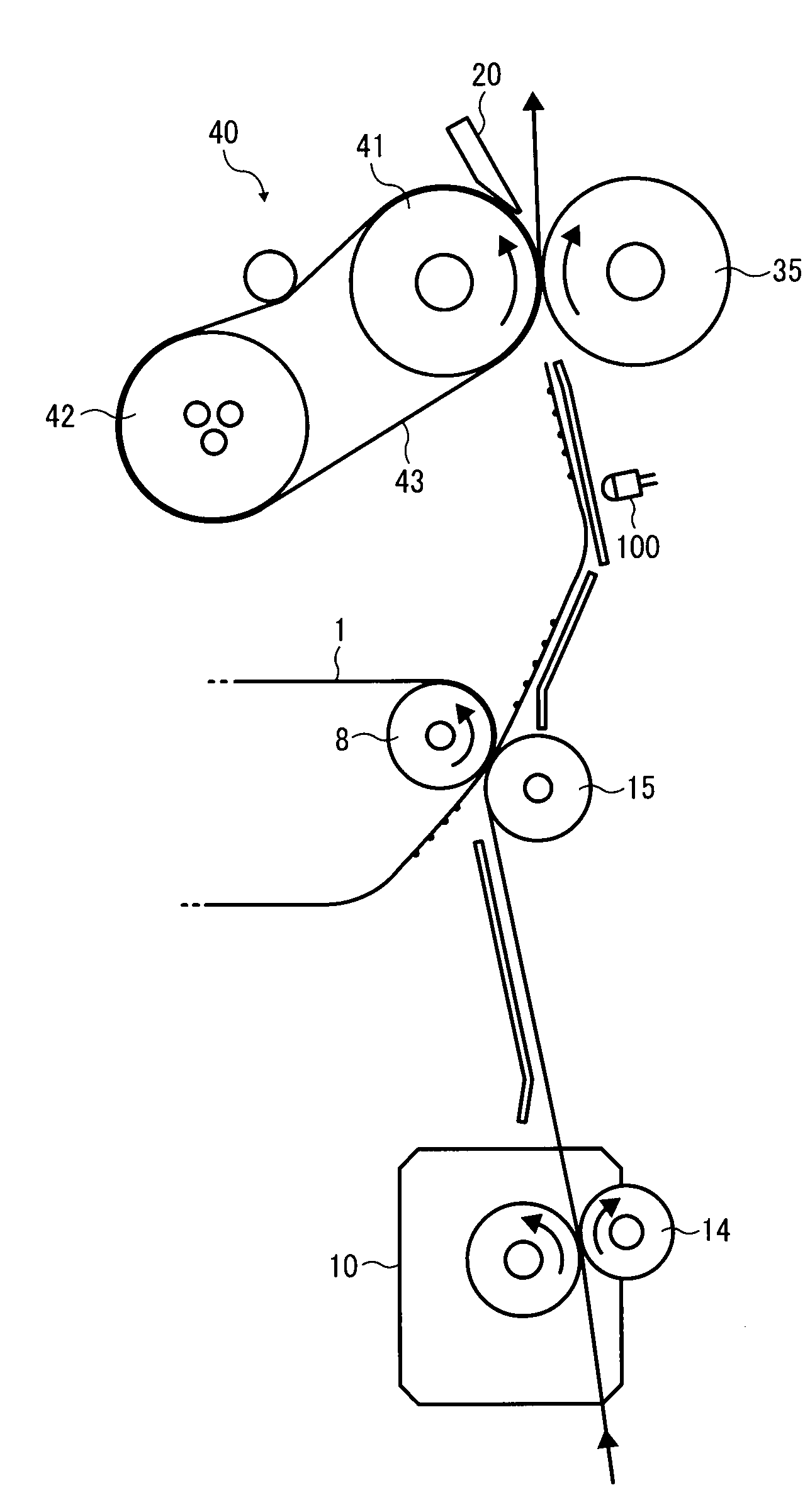
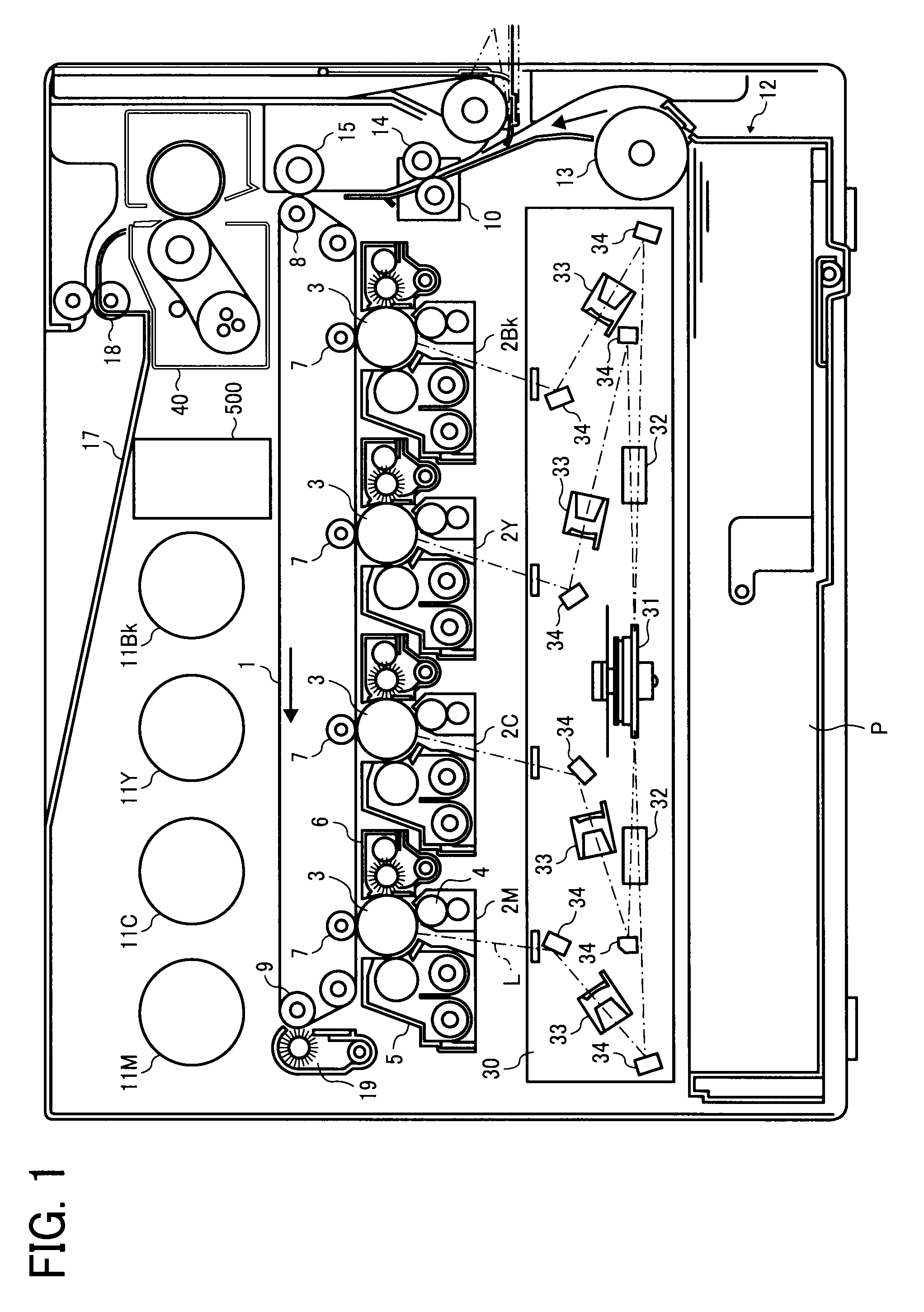
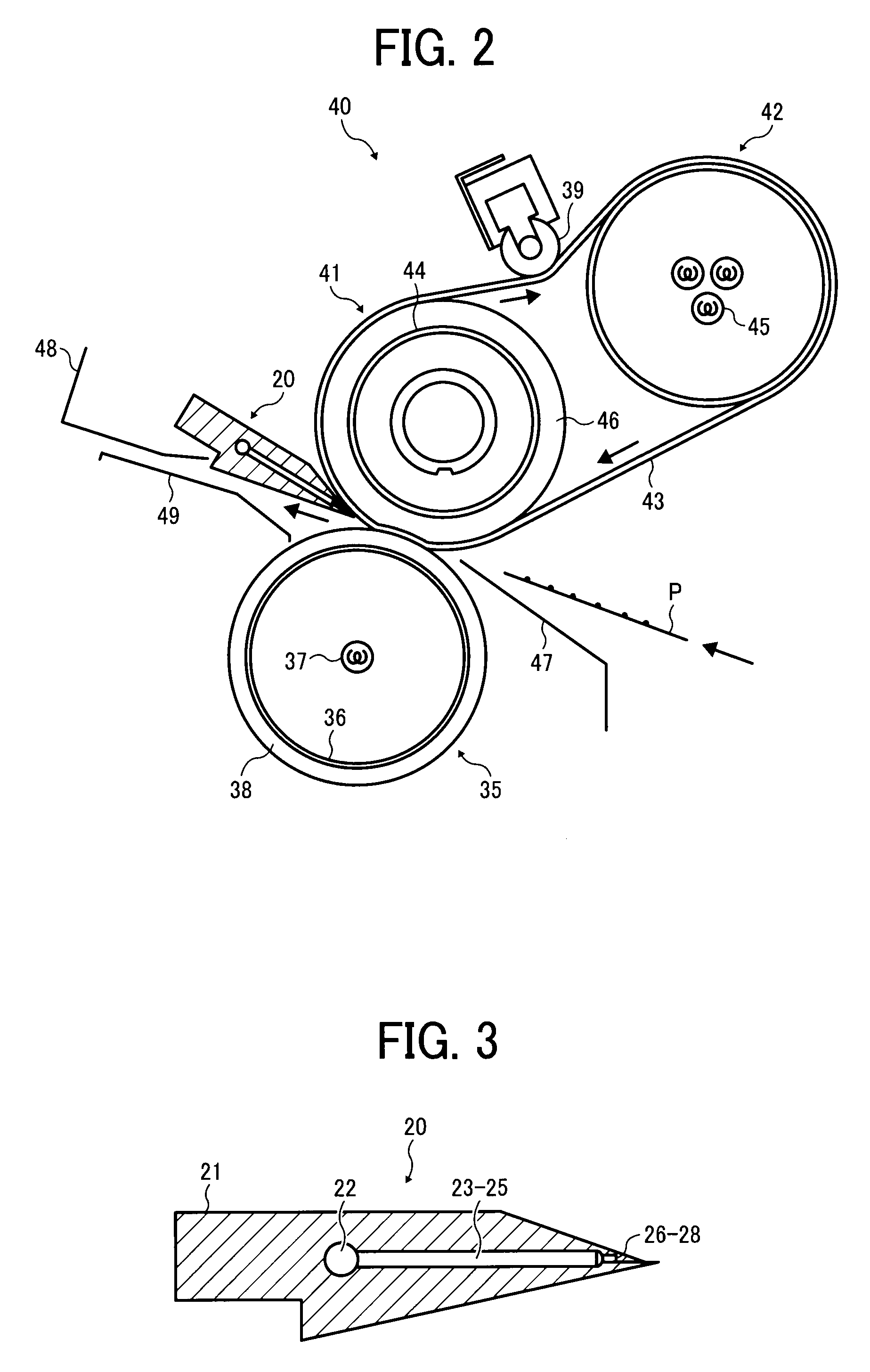
[0057]Typically, but not necessarily, paper is the medium from which is made a sheet on which an image is to be formed. It should be noted, however...


PUM


Abstract

An image forming apparatus includes an image forming station for forming an image, a registration member, a registration motor, and a fixing unit. The registration member is configured to feed the recording medium in appropriate timing such that a recording medium is aligned with the toner image formed in the image forming station. The registration motor is configured to drive the registration member. The fixing unit is configured to fix the toner image on the recording medium and includes a rotary heating member to heat the recording medium, a rotary pressure member to contact and press against the heating member forming a fixing nip portion where the heating roller and the pressure roller meet, and a sheet separator to eject air to separate the recording medium from the rotary heating member based on a drive signal of the registration motor.

Description

CROSS-REFERENCE TO RELATED APPLICATIONS[0001]This patent application is based on and claims priority pursuant to 35 U.S.C. §119 from Japanese Patent Application No. 2008-122124 filed on May 8, 2008 in the Japan Patent Office, the entire contents of which are hereby incorporated herein by reference.BACKGROUND OF THE INVENTION[0002]1. Field of the Invention[0003]Exemplary aspects of the present invention generally relate to an image forming apparatus, and more particularly, to an image forming apparatus including a fixing unit including a sheet separator using air.[0004]2. Description of the Background Art[0005]Conventionally, a generally known image forming apparatus employs a fixation method using a heating roller. In such a fixation method, heat and pressure are applied to a unfixed toner image on a recording sheet in a fixing nip portion where a pressure roller and a fixing roller including a halogen heater and so forth meet and press against each other while the recording sheet i...

Claims


Application Information

Patent Timeline
IPC IPC(8): G03G15/20G03G15/00
CPCG03G15/2028
Inventor ISHIKAWA, CHUUJI
Owner RICOH KK
Why Eureka
Try Eureka