Eureka AIR delivers breakthrough ideas for toughest innovation challenges, trusted by R&D personnel around the world.

Rechargeable battery

a rechargeable battery technology, applied in the field of rechargeable batteries, can solve the problems of generating a large stress between the electrode assembly and the core, deteriorating the life span of a part with concentrated stress, and thereby generating unstable reactions, so as to improve the structure and minimize the stress

Inactive Publication Date: 2009-11-12
SAMSUNG SDI CO LTD
View PDF2 Cites 8 Cited by
  • Summary
  • Abstract
  • Description
  • Claims
  • Application Information

AI Technical Summary

Benefits of technology

[0014]Aspects of the present invention provide a rechargeable battery having the advantage of an improved structure for minimizing stress between an electrode assembly and a core.
[0020]Since a space is formed between the core and the electrode assembly by a recessed portion formed at the core, stress between the electrode and the core can be reduced. Accordingly, it is possible to minimize output deterioration of the rechargeable battery.
[0021]Also, it is possible to easily reduce stress that is greatly generated at a center portion by forming the support members at both ends of the core and the variable member at the center thereof. Furthermore, structural stability can be sustained because the support members stably support the electrode assembly.
[0022]Furthermore, the support members are formed at both ends of the core, the variable members are formed at the center thereof, and the connection member is formed between the variable members. Therefore, stress between the electrode assembly and the core can be minimized.
[0023]Moreover, holes are formed at the core to allow elastic deformation. Therefore the output deterioration can be minimized by reducing the stress between the core and the electrode assembly.

Problems solved by technology

However, comparatively large stress is generated between the electrode assembly and the core because there is no margin space therebetween.
Also, the life-span of a part with concentrated stress deteriorates and unstable reaction is thereby generated.
Therefore, the life-span of the rechargeable battery is reduced due to the unstable reaction.

Method used


Image

  • Rechargeable battery
  • Rechargeable battery
  • Rechargeable battery

Examples


Embodiment Construction

[0038]Reference will now be made in detail to the present embodiments of the present invention, examples of which are illustrated in the accompanying drawings, wherein like reference numerals refer to the like elements throughout. The embodiments are described below in order to explain the present invention by referring to the figures.

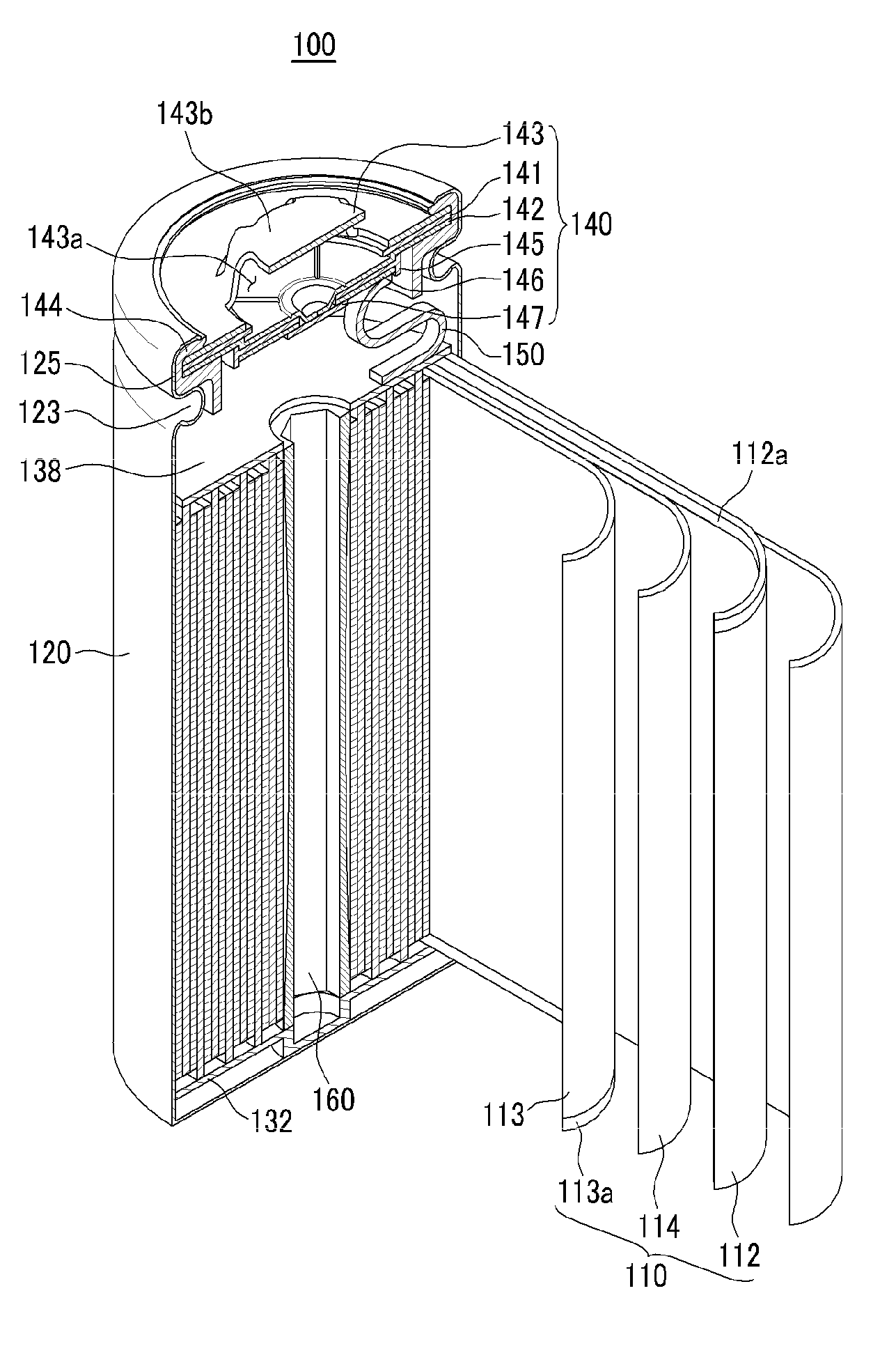
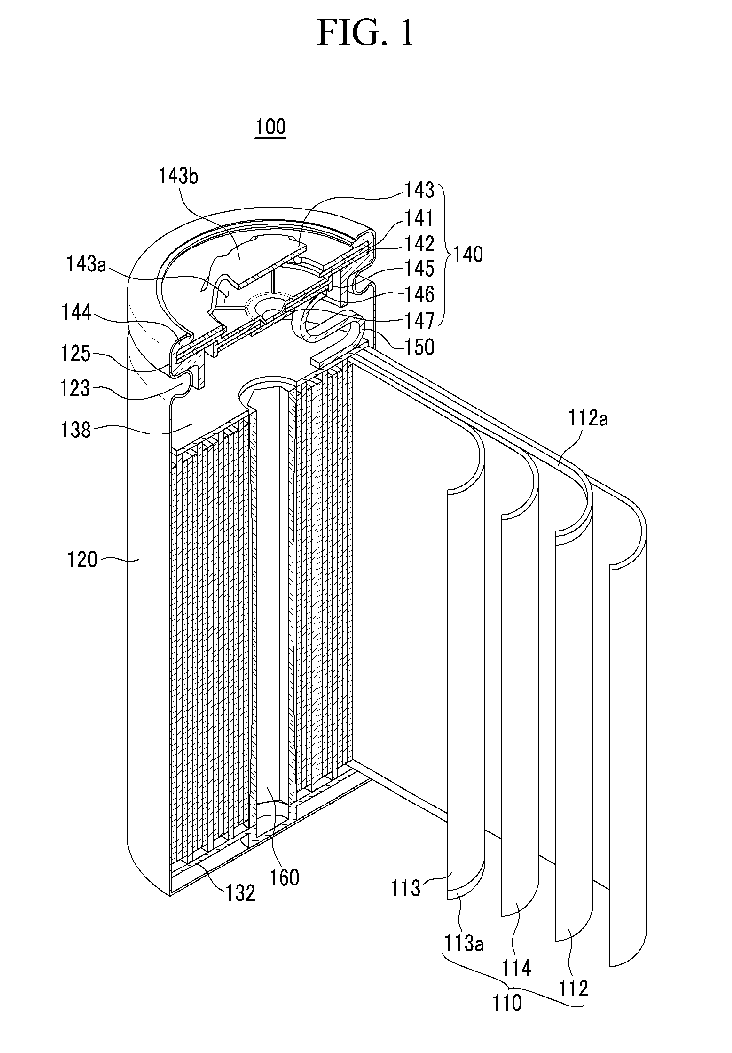
[0039]FIG. 1 is a cross-sectional perspective view of a rechargeable battery according to a first example embodiment of the present invention. The rechargeable battery 100 includes an electrode assembly 110 and a case 120. The electrode assembly 110 includes an anode 112, a cathode 113, and a separator 114 interposed between the anode 112 and the cathode 113. The case 120 includes an opening at one end thereof for housing the electrode assembly 110 along with an electrolyte solution. A cap assembly 140 is disposed at the opening of the case 120 for sealing the case 120 with a gasket 144 as an interface.

[0040]The case 120 is made of a conductive metal s...


PUM

PropertyMeasurementUnit
exterior diameteraaaaaaaaaa
lengthaaaaaaaaaa

Abstract

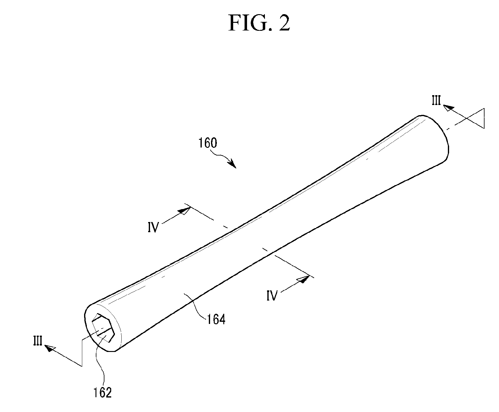
A rechargeable battery including an electrode assembly, a case, a cap assembly, and a core. The electrode assembly includes an anode, a cathode, and a separator interposed between the anode and the cathode. The case has a space for housing the electrode assembly. The cap assembly is connected to the case and electrically connected to the electrode assembly. The core is disposed inside the electrode assembly, and has a distance between the exterior and the center thereof at one end in a length direction that is greater than a distance between the exterior and the center thereof at the center in the length direction.

Description

CROSS-REFERENCE TO RELATED APPLICATION[0001]This application claims the benefit of Korean Patent Application No. 2008-42399, filed May 7, 2008 in the Korean Intellectual Property Office, the disclosure of which is incorporated herein by reference.BACKGROUND OF THE INVENTION[0002]1. Field of the Invention[0003]Aspects of the present invention relate to a rechargeable battery. More particularly, aspects of the present invention relate to a rechargeable battery having an improved core structure disposed in an electrode assembly.[0004]2. Description of the Related Art[0005]A rechargeable battery can be discharged in use and recharged, unlike a primary battery that cannot be recharged. A low-capacity rechargeable battery is formed of one cell. Low-capacity rechargeable batteries have been used for portable small electronic devices such as mobile phones, laptop computers and camcorders. A large capacity rechargeable battery includes a plurality of cells that are connected in a form of a p...

Claims


Application Information

Patent Timeline
Patent Type & Authority Applications(United States)
IPC IPC(8): H01M2/02H01M50/469
CPCH01M10/0431H01M2/18Y02E60/10Y02P70/50H01M50/469H01M50/463H01M10/0587
Inventor HAN, DAE-WONKIM, YONG-SAMBYUN, SANG-WONAHN, BYUNG-KYUKIM, SUNG-BAEKIM, KI-HOPARK, ZINKOGURE, MASANORIYOON, SEOK-JOON
Owner SAMSUNG SDI CO LTD
Why Eureka
Eureka Blog
Learn More