
Device for secretion removal, manual ventilation and determination of in vivo lung mechanics without circuit disconnection

a technology of in vivo lung mechanics and in vivo secretion removal, which is applied in the field of medical devices, can solve the problems of no real-time in vivo monitoring methods or devices, lag time of tests averaging 30 minutes to 2 hours post-treatment, and patient coughing

Inactive Publication Date: 2009-11-12
ESTETTER ROBERT H
View PDF3 Cites 3 Cited by
  • Summary
  • Abstract
  • Description
  • Claims
  • Application Information

AI Technical Summary

Problems solved by technology

Currently, in-line lung suction devices allow secretions to be deposited into the ventilator circuit and heat / moisture exchange devices, with the instillation of saline in the lung and resulting coughing by the patient.
This results in secretions being delivered to the patient rather than being removed.
There currently are no real-time in vivo monitoring methods or devices for determining the optimal lung inflation facilitating sub-tidal volume delivery (Vtsub) during high frequency ventilation (HFV).
However, results of these tests suffer from lag times averaging 30 minutes to 2 hours post-patient de-compensation.
This lack of real-time feedback in HFV management allows for a probability of facilitating ventilator-induced lung injury (VILI) and may cause hemodynamic compromise to the patient secondary to alveolar over-distention affecting cardiac output.
Measurements which require disconnection of the high frequency ventilator allow for de-recruitment of the patient's lungs such that the hysteresis of the lung skews any measurements obtained; thereby resulting in measurements which do not reflect actual conditions.
Furthermore, during periods of patient de-compensation it is difficult to rule out pulmonary causes or issues associated with the artificial airway.
This delay can result in needless, wrong, or delayed ventilator changes, or unwarranted patient disconnects (i.e., manual ventilation or endotracheal suctioning) that can worsen patient de-compensation.
Patient disconnection has also been shown to increase incidence of ventilator-acquired pneumonia (VAP) and patient de-compensation due to lung de-recruitment and cardiac function compromise.

Method used


Image

  • Device for secretion removal, manual ventilation and determination of in vivo lung mechanics without circuit disconnection
  • Device for secretion removal, manual ventilation and determination of in vivo lung mechanics without circuit disconnection
  • Device for secretion removal, manual ventilation and determination of in vivo lung mechanics without circuit disconnection

Examples


third embodiment

[0044]Referring now to FIGS. 4A-4D, illustrated are sectional views of a pulmonary mechanics measuring device 400 comprising a rotating valve assembly. The compliance measuring device 400 comprises a valve assembly 410 used to control communication with the standard endotracheal tube 118. The valve assembly 410 comprises at least one circular shaped rigid body 411, a rotatable plate 412 and a solid pin assembly 413. The rotatable plate 412 has a plurality of orifices 421-423 therethrough and rotates around the solid pin assembly 413. The plurality of orifices 421-423 are first, second and third positional ports 421-423, respectively. The first positional port 421 (FIG. 4A) is a ventilation port which enables uninterrupted ventilation to the patient when positioned inline of the in-patient ventilator circuitry (endotracheal tube 118) by means of ventilator 430. The second positional port 422 is a suction port enabling endotracheal suctioning when positioned inline of the in-patient v...

fourth embodiment

[0045]Referring now to FIGS. 5A and 5B, illustrated are sectional views of a pulmonary mechanics measuring device 500 constructed according to the principles of the present invention. The pulmonary mechanics measuring device 500 comprises a rigid body chamber 510, a ventilation port 504, an ETT port 511, and a hinged valve assembly 520. In this embodiment, the valve assembly 520 is hinged at a point 521 so that the valve will rotate into an obstructed position as shown in FIG. 5B thereby occluding ventilation by the HFV (not shown). A flexible sleeve 522 envelops the valve assembly 520. Ventilation port 504 couples to the HFV (not shown) and provides ventilation when not obstructed by the hinged valve 520. The patient's endotracheal tube 118 is coupled at ETT port 511. Port 526 may be used for measuring pressure as described above. Port 506 may also be fluidly coupled to port 526 or simply in addition to port 526 to provide a means for instilling a known volume of gas as described a...

fifth embodiment

[0046]Referring now to FIGS. 6A and 6B, illustrated are sectional views of a pulmonary mechanics measuring device 600 and elevation views of a gate valve constructed according to the principles of the present invention. The pulmonary mechanics measuring device 600 comprises a rigid body chamber 610, a ventilation port 604, an ETT port 611, and a gate valve assembly 620. The gate valve 620 may be either manual or solenoid operated. Ventilation port 604 couples to the HFV (not shown) and provides ventilation when not obstructed by the gate valve 620. The patient's endotracheal tube 118 is coupled at ETT port 611. When gate valve 620 is closed, port 626 may be used for measuring pressure as described above. Port 606 may also be fluidly coupled to port 626 or simply in addition to port 626 to provide a means for instilling a known volume of gas as described above. The rigid body chamber 610 may be shaped so as to provide port 625 with a more direct access for insertion of a flexible cat...


PUM

PropertyMeasurementUnit
volumeaaaaaaaaaa
volumeaaaaaaaaaa
tidal volumesaaaaaaaaaa

Abstract

An artificial airway obstruction and pulmonary mechanics measuring device comprising a rigid body chamber having a pressure measuring port and a medical ventilator port; a pressure measuring device coupled to the pressure measuring port; and a ventilator port occlusion device coupleable to the medical ventilator port. A method of manufacturing an artificial airway obstruction and pulmonary mechanics measuring device is included.

Description

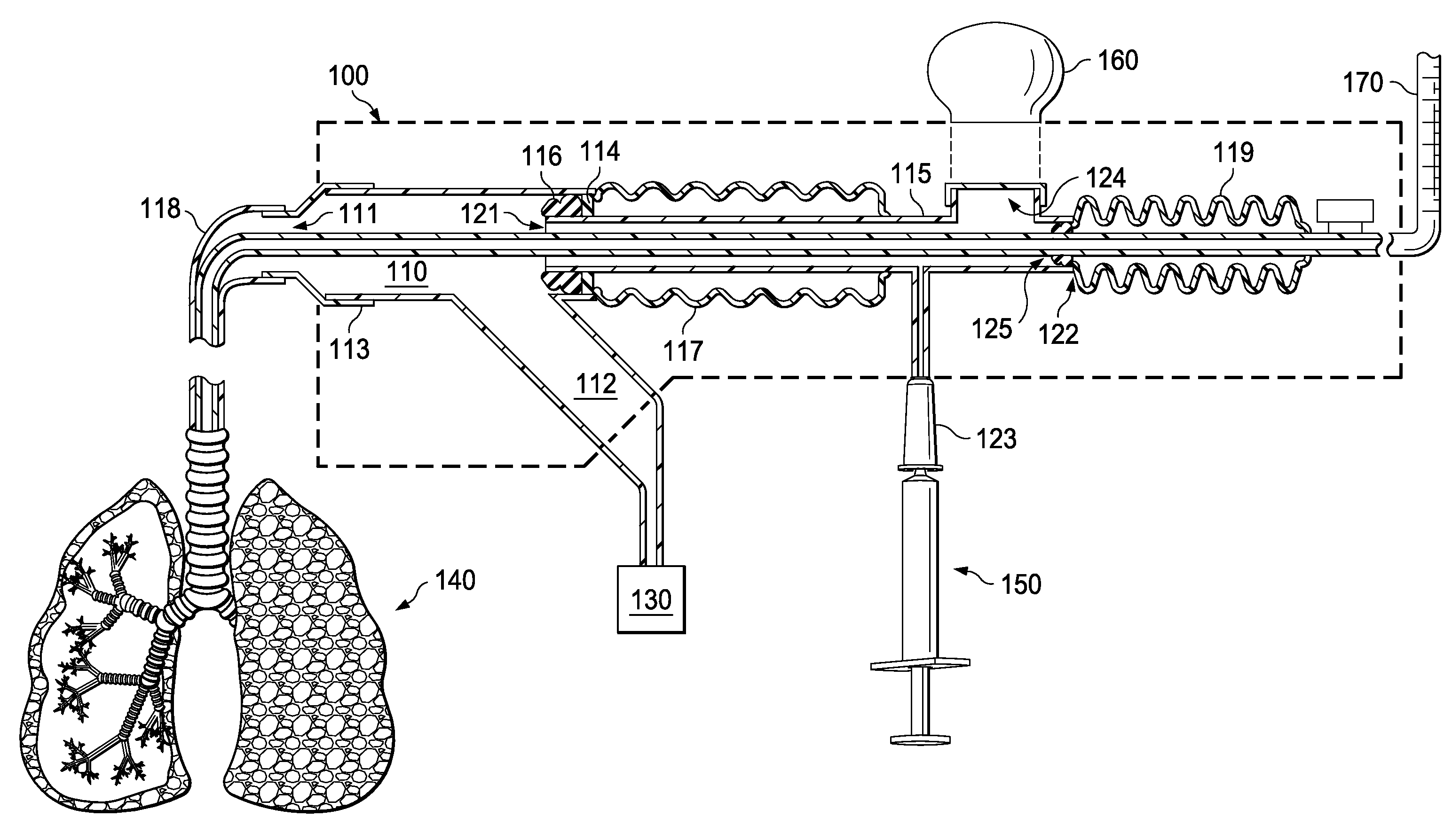
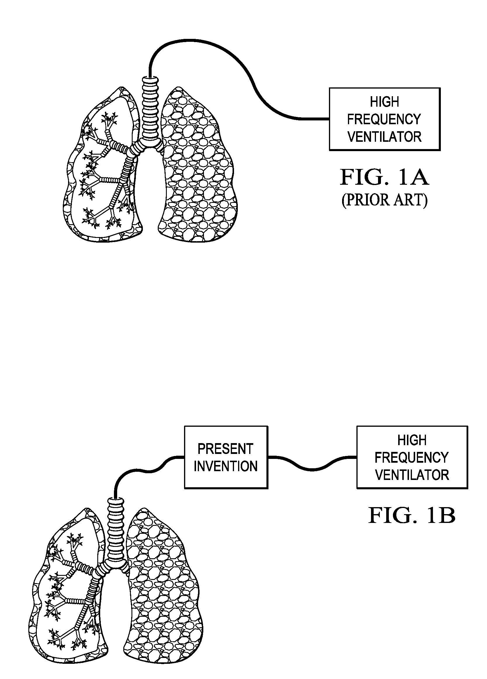
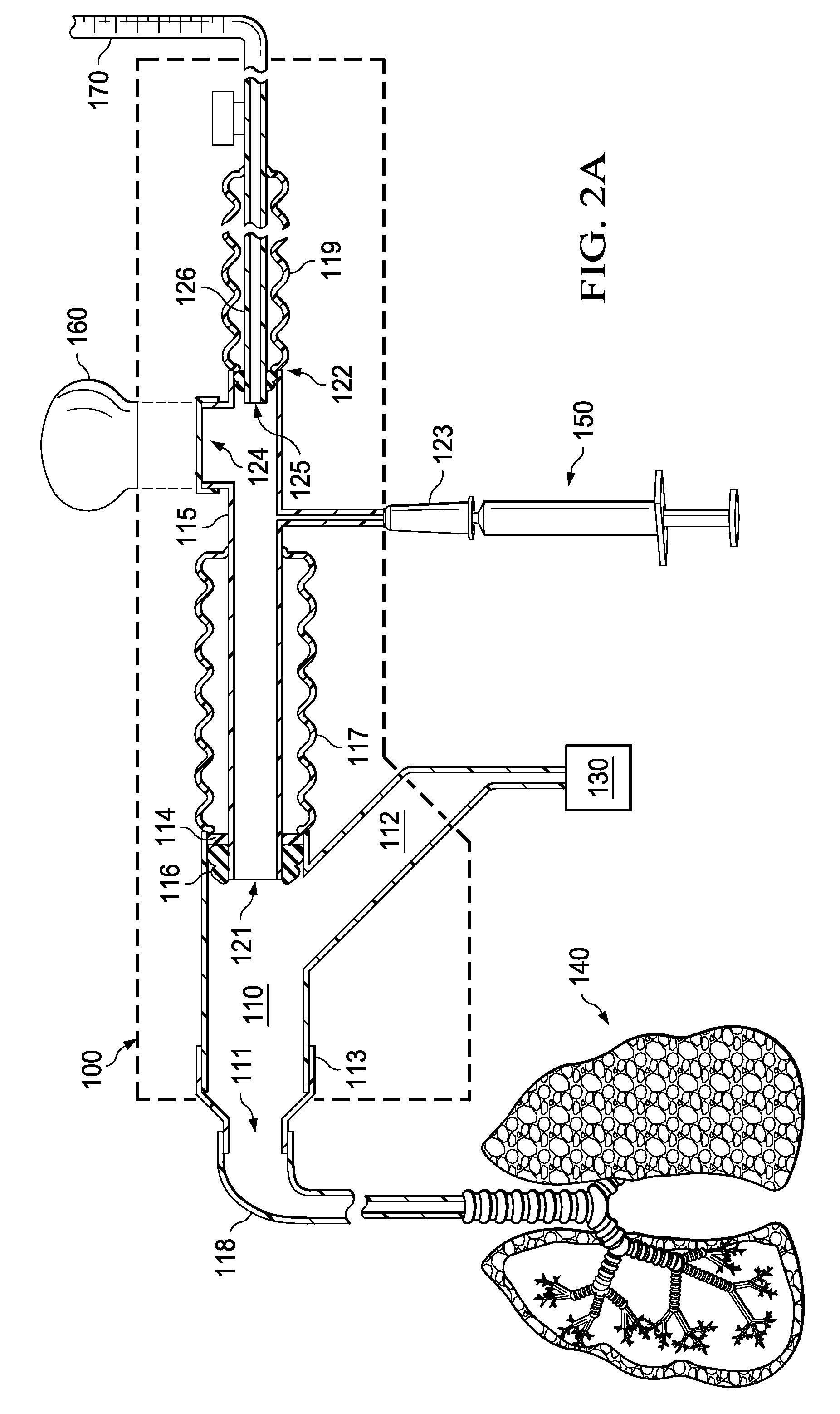
CROSS-REFERENCE TO PROVISIONAL APPLICATION[0001]This application claims the benefit of U.S. Provisional Application No. 61 / 051,389 entitled “DEVICE FOR SECRETION REMOVAL, MANUAL VENTILATION AND DETERMINATION OF IN VIVO LUNG MECHANICS WITHOUT CIRCUIT DISCONNECTION” to Estetter, filed on May 8, 2008 which is commonly owned with the present invention and incorporated herein by reference as if reproduced herein in its entirety.TECHNICAL FIELD OF THE INVENTION[0002]The present invention is directed, in general, to a medical device and, more specifically, to a device and method for in vivo secretion removal and manual ventilation of human lungs as well as determination of in vivo lung mechanics without circuit disconnection of a mechanical ventilator.BACKGROUND OF THE INVENTION[0003]Currently, in-line lung suction devices allow secretions to be deposited into the ventilator circuit and heat / moisture exchange devices, with the instillation of saline in the lung and resulting coughing by th...

Claims


Application Information

Patent Timeline
Patent Type & Authority Applications(United States)
IPC IPC(8): A61B5/087B23P11/00
CPCY10T29/49826A61B5/087
Inventor ESTETTER, ROBERT H.
Owner ESTETTER ROBERT H
Learn More