Expander and heat pump using the expander

a technology of expander and expansion pump, which is applied in the field of expansion pump, can solve the problems of inability to recover the energy of expansion of working fluid that passes through the sub-circuit, the inability to control the refrigeration cycle freely, and the inability to efficiently operate the refrigeration cycle, so as to achieve the control of the rotation speed of the expander, the effect of efficient energy recovery of working fluid and high power generation efficiency

Inactive Publication Date: 2009-11-19
PANASONIC CORP
View PDF7 Cites 15 Cited by
  • Summary
  • Abstract
  • Description
  • Claims
  • Application Information

AI Technical Summary

Benefits of technology

[0012]The present invention has been accomplished in view of the foregoing circumstances, and it is an object of the invention to provide an expander capable of recovering the energy of expansion of the working fluid efficiently. It is another object of the present invention to provide a heat pump using the expander.
[0021]According to the expander of the present invention, it is possible to adjust the timing for shifting from the suction process for the working fluid to the expansion process for the working fluid by changing the connection position at which the suction-side space of the first expansion mechanism and the second suction port. Specifically, it is possible to control the ratio of the time length for which the expansion process is performed to the time length for which the suction process is performed. As a result, according to the present invention, it becomes possible to change the foregoing ratio (Ves / Vcs), and for example, it is possible to avoid the constraint of constant density ratio in a refrigeration cycle employing an expander-compressor unit. Therefore, the energy of expansion of the working fluid can be recovered efficiently by allowing the entire working fluid to flow into the expander without providing a sub-circuit for the working fluid.
[0022]When using the expander according to the present invention as a separate-type expander, the rotation speed of the expander can be controlled while at the same time maintaining the amount of the working fluid flowing into the expander. As a result, it becomes easy to set the rotation speed of the power generator connected to the expander in the vicinity of the rated rotation speed to maintain a high power generation efficiency by the power generator.

Problems solved by technology

Thus, the refrigeration cycle is hindered from being controlled freely.
Therefore, the refrigeration cycle cannot be operated efficiently if the temperature and the pressure cannot be controlled freely.
In this configuration, however, the energy of expansion of the working fluid that passes through the sub-circuit cannot be recovered.
The problem of the inefficiency in recovering the energy of expansion of the working fluid is noticeable in the case of using an expander-compressor unit, but the problem also arises in the case of using a separate-type expander, which is not coupled to a compressor by a shaft.
In a refrigeration cycle, however, the circulation amount and the density of the working fluid change depending on the operation conditions, so it is difficult to operate the power generator only in the vicinity of the rated rotation speed.
Thus, even in the separate-type expander, achieving efficient recovery of the energy of expansion of the working fluid is not easy.

Method used


Image

  • Expander and heat pump using the expander
  • Expander and heat pump using the expander
  • Expander and heat pump using the expander

Examples


first embodiment

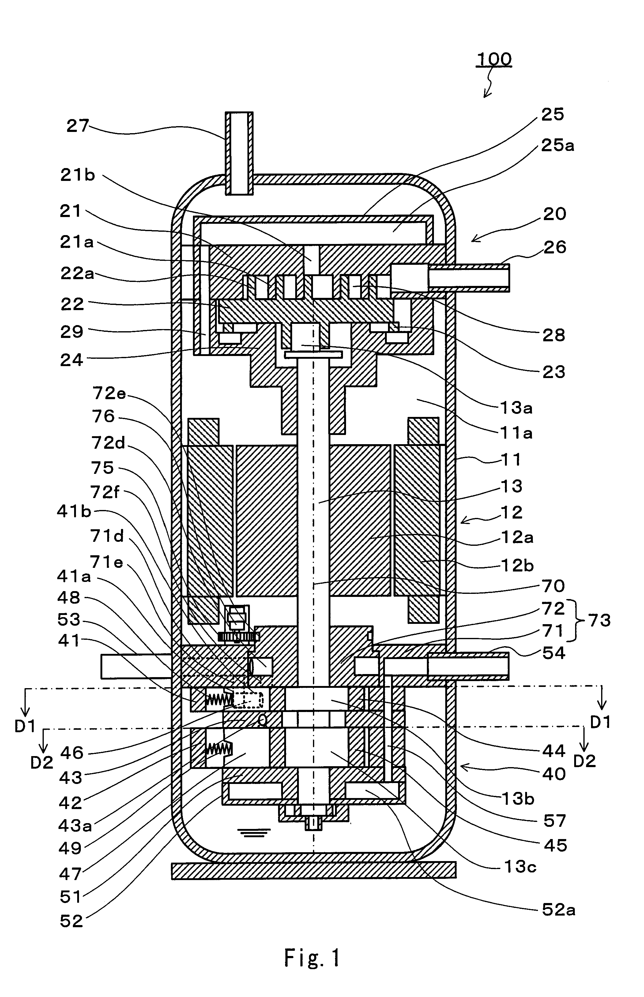
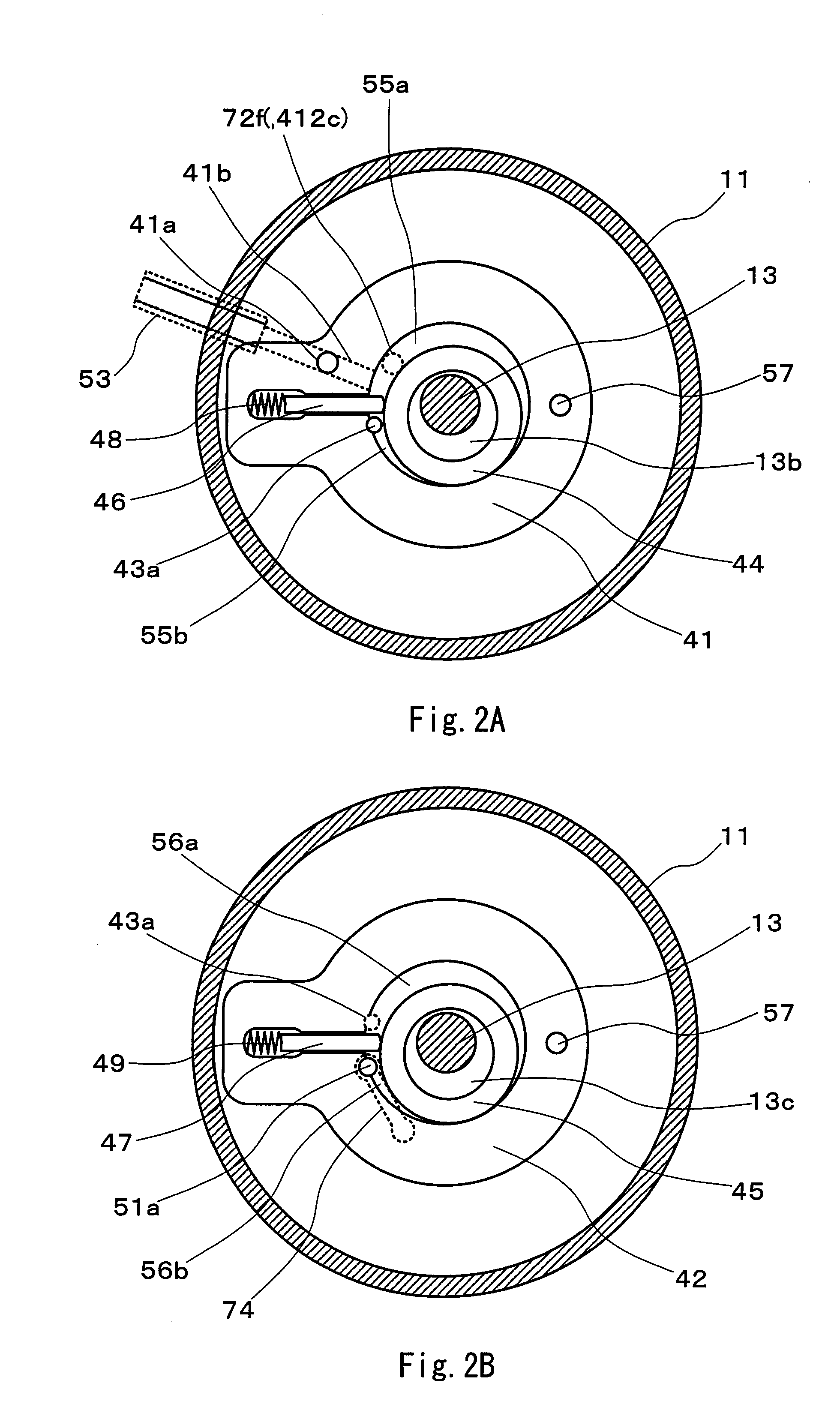
[0055]FIG. 1 is a vertical cross-sectional view illustrating an expander-compressor unit according to a first embodiment of the present invention. FIG. 2A is a horizontal cross-sectional view of an expander section of the expander-compressor unit shown in FIG. 1, taken along line D1-D1 of FIG. 1. FIG. 2B is a horizontal cross-sectional view of the expander section of the expander-compressor unit, taken along line D2-D2. FIG. 3A is a perspective partial cut-away view of a stationary portion of an upper end plate of the expander section. FIG. 3B is a perspective view of a movable portion of the upper end plate. FIG. 3C is a perspective partial cut-away view illustrating the upper end plate in which the stationary portion and the movable portion have been integrated.

[0056]An expander-compressor unit 100 according to the present embodiment includes a closed casing 11, a scroll type compressor section 20 disposed in an upper portion of the closed casing, a two-stage rotary expander secti...

second embodiment

[0100]As has been mentioned in the foregoing embodiment, the position of the second suction port for varying the suction volume of the expander can be varied by an actuator that makes use of pressure difference of a fluid. The actuator making use of pressure difference of a fluid enhances reliability under severe conditions, such as under a high temperature, high pressure environment. Another advantage is that the working fluid that should be expanded by an expander can be utilized as it is for the power source of the actuator. The present embodiment describes a variable suction volume-type expander including such an actuator. In the present embodiment, the same components as described in the first embodiment are designated by the same reference numerals.

[0101]FIG. 11 is a vertical cross-sectional view illustrating an expander according to the second embodiment. As illustrated in FIG. 11, an expander 303 is a rotary type expander. The expander 303 includes a closed casing 11, a powe...

third embodiment

[0142]The features of the expander illustrated in the second embodiment may be employed suitably for an expander-compressor unit in which an expander section and a compressor section are integrated with each other by a shaft, as explained in the first embodiment. FIG. 17 is a vertical cross-sectional view illustrating such an expander-compressor unit.

[0143]An expander-compressor unit 700 includes a closed casing 11, a scroll type compressor section 20 disposed in an upper portion of the closed casing 11, a two-stage rotary expander section 400 disposed in a lower portion of the closed casing 11, a rotation motor 12 disposed between the compressor section 20 and the expander section 400, and a shaft 13 commonly used for the compressor section 20, the expander section 400, and the rotation motor 12. As the rotation motor 12 drives rotation of the shaft 13, the compressor section 20 operates. This expander-compressor unit 700 makes use of the rotational force imparted to the shaft 13 b...


PUM


Abstract

An expander of the invention includes: n-number of rotary type fluid mechanisms (where n is an integer equal to or greater than 2), a first suction port (41b) for sucking a working fluid into a suction-side space (55a) of a first fluid mechanism (41), a communication port (43a) connecting a discharge-side space (55b) of a k-th fluid mechanism (where k is an integer from 1 to n−1) and a (k+1)-th suction-side space (56a) to form a single space, and a discharge port (51a) for discharging the working fluid from the discharge-side space of an n-th fluid mechanism. The expander further includes a second suction port (72f) being capable of changing its connecting position to the suction-side space (55a) of the first fluid mechanism (41), for sucking the working fluid into the suction-side space (55a).

Description

TECHNICAL FIELD[0001]The present invention relates to an expander applied to a refrigeration cycle apparatus (heat pump), and more particularly to a heat pump using the expander.BACKGROUND ART[0002]A power recovery type refrigeration cycle in which the energy of expansion of a working fluid (refrigerant) is recovered by an expander and the recovered energy is made use of as a part of the work of a compressor has been proposed. A refrigeration cycle that employs a fluid machine in which an expander and a compressor are coupled to each other by a shaft (hereinafter also referred to as an “expander-compressor unit”) has been known as such a refrigeration cycle. (See JP 2001-116371A).[0003]Hereinbelow, the refrigeration cycle employing the expander-compressor unit is described.[0004]FIG. 20 shows a refrigeration cycle using the conventional expander-compressor unit. In this refrigeration cycle, a main circuit 8 for a working fluid (refrigerant) is constituted by a compressor 1, a gas co...

Claims


Application Information

Patent Timeline
Patent Type & Authority Applications(United States)
IPC IPC(8): F01C1/02F01C13/04F25B11/02F25B9/06F25B30/02
CPCF01C1/3564F01C11/002F01C11/008F01C13/04F01C20/16F01C21/18F25B2309/061F04C23/006F04C23/008F25B1/04F25B9/008F25B9/06F04C18/0215
Inventor HASEGAWA, HIROSHIMATSUI, MASARUOKAICHI, ATSUOTAMURA, TOMOICHIROOGATA, TAKESHIMATSUI, KEIZOMATSUYAMA, TETSUYA
Owner PANASONIC CORP
Why Eureka
Try Eureka