
Dual beam dual selectable polarization antenna

a polarization antenna and dual beam technology, applied in the field of antennas, can solve the problems of affecting the size and complexity of the antenna, the design of the phased array antenna may be too large to fit within the space, and the different components of the phased array antenna may be limited

Active Publication Date: 2009-11-19
THE BOEING CO
View PDF15 Cites 43 Cited by
  • Summary
  • Abstract
  • Description
  • Claims
  • Application Information

AI Technical Summary

Problems solved by technology

With phased array antenna systems, the size and complexity of an antenna may be a concern depending on the use.
In some uses, the amount of room for the different components in a phased array antenna may be limited.
As a result, some phased array antenna designs may be too large to fit within the space that may be allocated for a phased array antenna.

Method used


Image

  • Dual beam dual selectable polarization antenna
  • Dual beam dual selectable polarization antenna
  • Dual beam dual selectable polarization antenna

Examples


Embodiment Construction

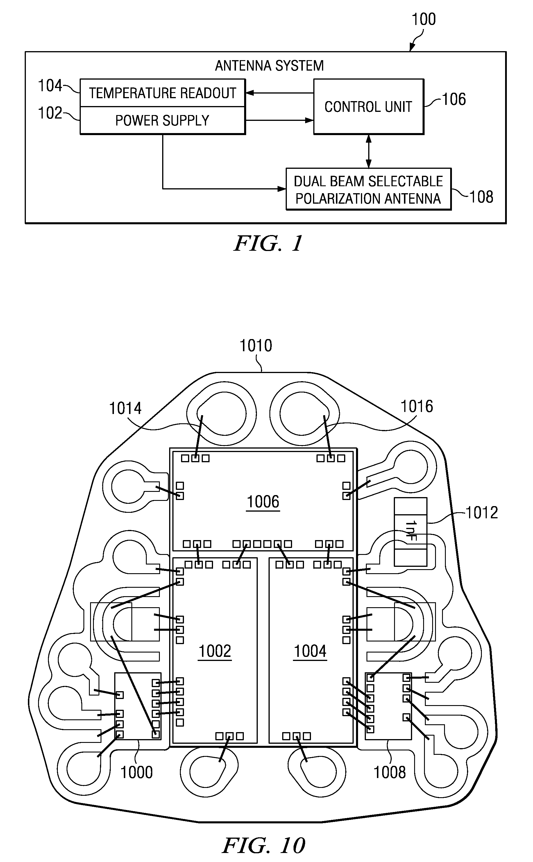
[0023]With reference now to the figures and in particular with reference now to FIG. 1, a diagram illustrating a configuration of an antenna system is depicted in accordance with an advantageous embodiment. In this example, antenna system 100 comprises power supply 102, temperature readout 104, control unit 106, and dual beam selectable polarization antenna 108. In these examples, power supply 102 provides power to control unit 106 and dual beam selectable polarization antenna 108.

[0024]Control unit 106 controls the array pointing angle and polarization for each of the beams that may be generated by dual beam selectable polarization antenna 108. In other words, dual beam selectable polarization antenna 108 may generate two beams of directive radiation. Each of these beams may be pointed in different directions and may have a different polarization.

[0025]For example, one beam may have a right-hand circular polarization and may be directed at an angle around 60, and 90 (theta, phi) de...


PUM


Abstract

A dual beam dual-selectable-polarization phased array antenna comprises an aperture unit, a printed wiring board, radiating elements, chip units, a pressure plate, and a rear housing unit. The printed wiring board has sub assemblies bonded to each other with a bonding material providing both mechanical and electrical connection. The printed wiring board is connected to the aperture unit. The radiating elements are formed on the printed wiring board. The chip units are mounted on the printed wiring board. The chip units include circuits capable of controlling radio frequency signals radiated by the radiating elements to form dual beams with independently selectable polarization. The pressure plate is connected to the aperture unit. The aperture unit is connected to the rear housing unit such that the aperture unit covers the rear housing unit.

Description

GOVERNMENT LICENSE RIGHTS[0001]This invention was made with Government support under prime contract number F19628-00-C-0002 between MIT / Lincoln Labs and the Government. The Boeing Company is the subcontractor for this invention under contract number 3039171. The Government has certain rights to this invention.BACKGROUND INFORMATION[0002]1. Field[0003]The present disclosure is directed towards antennas and in particular to phased array antennas. Still more particularly, the present disclosure relates to a phased array antenna having a tile architecture.[0004]2. Background:[0005]A phased array antenna is a group of antennas in which the relative phases of the respective signals feeding the antennas may be varied in a way that the effect of radiation pattern of the array is reinforced in a desired direction and suppressed in undesired directions. In other words, one or more beams may be generated that may be pointed in or steered into different directions. A beam pointing in a transmit...

Claims


Application Information

Patent Timeline
IPC IPC(8): H01Q3/00
CPCH01Q23/00H01Q21/061H01Q21/0025
Inventor WORL, ROBERT TILMANBEKKER, ISAAC RONMILLER, DAN R.VOYCE, KENNETH G.CHEN, MINGREDD, HAROLD J.
Owner THE BOEING CO
Learn More