Liquid crystal display apparatus

a technology of liquid crystal display and display apparatus, which is applied in the direction of instruments, non-linear optics, optics, etc., can solve the problems of reducing the size of pixels, reducing and limiting the number of electrodes which can be provided for one pixel in the corresponding display apparatus

Inactive Publication Date: 2009-11-19
PANASONIC LIQUID CRYSTAL DISPLAY CO LTD +1
View PDF5 Cites 46 Cited by
  • Summary
  • Abstract
  • Description
  • Claims
  • Application Information

AI Technical Summary

Benefits of technology

[0015]Additionally, in the present embodiment, in the transmission area, of the pixel electrode or the common electrode, the electrode formed at a side more distant from the liquid crystal layer is planarly formed, whereas in the reflection area, of the pixel electrode or the common electrode, the electrode formed at a side more distant from the liquid crystal layer includes an aperture in a planarly formed electrode layer.
[0016]Another liquid crystal display apparatus according to the present invention comprises: a liquid crystal display panel including a first substrate, a second substrate, a liquid crystal layer held in a sandwiched condition between the substrates, and a pixel electrode and common electrode disposed on the second substrate in order to drive the liquid crystal layer; a backlight disposed on one face of the liquid crystal display panel; a first polarizer disposed on one face of the first substrate, at a side opposite to the second substrate; and a second polarizer disposed on one face of the second substrate, at a side opposite to the first substrate. The liquid crystal layer has a property of generating optical anisotropy from an optical isotropic state when a voltage is applied. The liquid crystal display panel includes a transmission area and a reflection area in one pixel. In the reflection area, one of the pixel electrode and the common electrode is formed into a comb shape or includes a slit-shaped aperture in an electrode layer formed into a planar shape, with the other electrode being formed planarly on a different layer via an insulation layer, and an electric field formed in the liquid crystal layer according to a particular voltage difference between the pixel electrode and the common electrode will be weaker in the reflection area than in the transmission area. In the reflection area, the display panel further includes an in-cell retardation layer between the liquid crystal layer and the first or second substrate.
[0017]Yet another liquid crystal display apparatus according to the present invention comprises: a liquid crystal display panel including a first substrate, a second substrate, a liquid crystal layer held in a sandwiched condition between the substrates, and a pixel electrode and common electrode disposed on the second substrate in order to drive the liquid crystal layer; a backlight disposed on one face of the liquid crystal display panel; a first polarizer disposed on one face of the first substrate, at a side opposite to the second substrate; and a second polarizer disposed on one face of the second substrate, at a side opposite to the first substrate. The liquid crystal layer has a property of generating optical anisotropy from an optical isotropic state when a voltage is applied. The liquid crystal display panel includes a transmission area and a reflection area in one pixel; in the reflection area, the display panel includes a reflective layer between the pixel electrode, the common electrode, and the second substrate, and at least in the reflection area, further includes a polarizing layer between the reflective layer and the liquid crystal layer. The first polarizer has an absorption axis perpendicular to an absorption axis of the second polarizer, and the polarizing layer has an absorption axis parallel to the absorption axis of the second polarizer.

Problems solved by technology

The number of electrodes which can be provided for one pixel in the corresponding display apparatus is limited according to the particular accuracy of its manufacturing apparatus such as an exposure apparatus.
For a high-resolution liquid crystal display apparatus, in particular, the size of pixels decreases, so several electrodes can only be provided in one pixel of space.
This, in turn, limits the achievable inter-electrode clearances, making it difficult for the relationship in the magnitude of the electric field strength between the reflection area and the transmission area to satisfy desired conditions.
In addition, as discussed above, the properties of isotropic liquid crystals that differ from those of conventional liquid crystals are coming to be elucidated, but the structure of the display apparatus applying the above liquid crystal material is not fully studied.

Method used


Image

  • Liquid crystal display apparatus
  • Liquid crystal display apparatus
  • Liquid crystal display apparatus

Examples


first embodiment

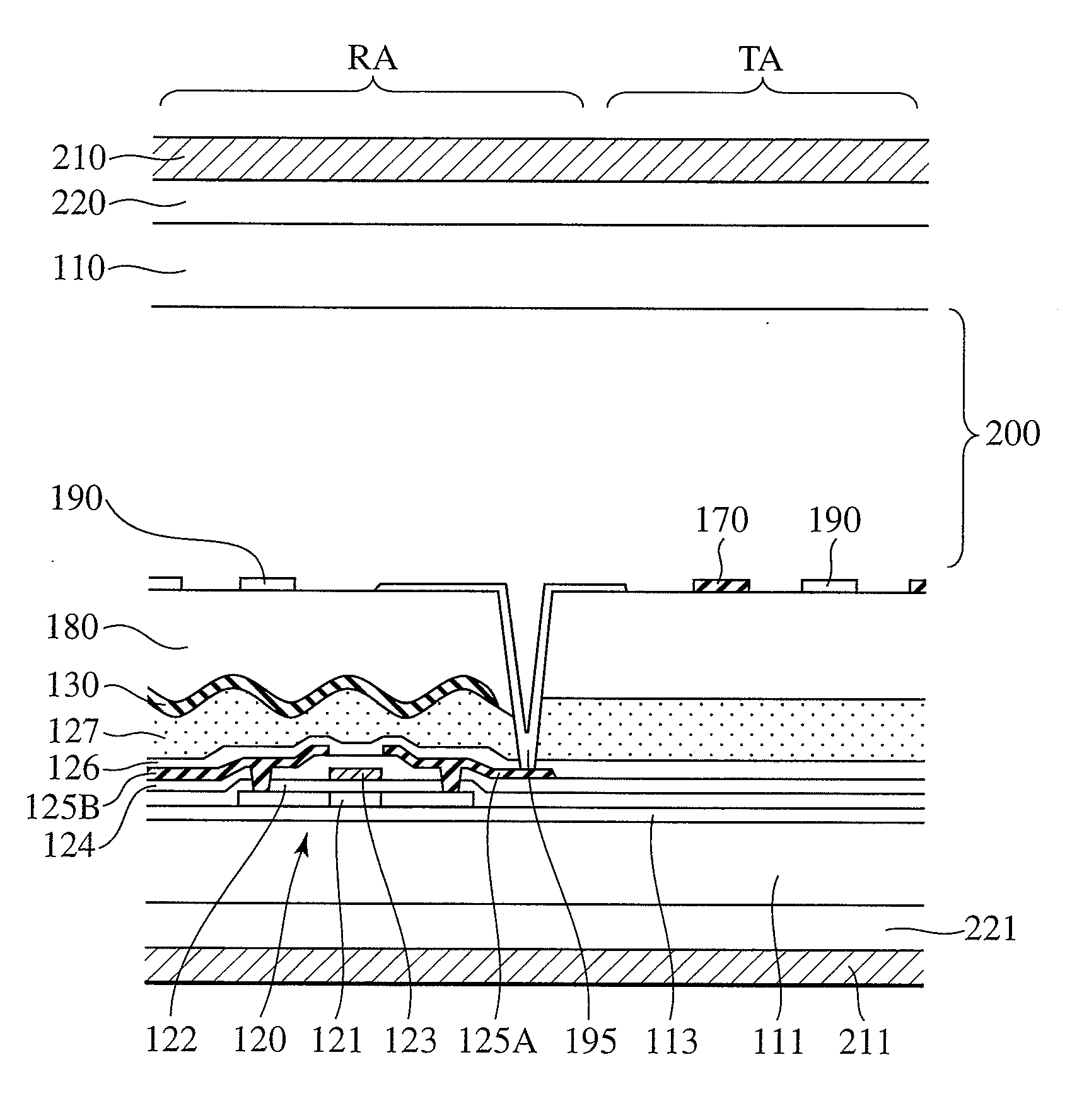
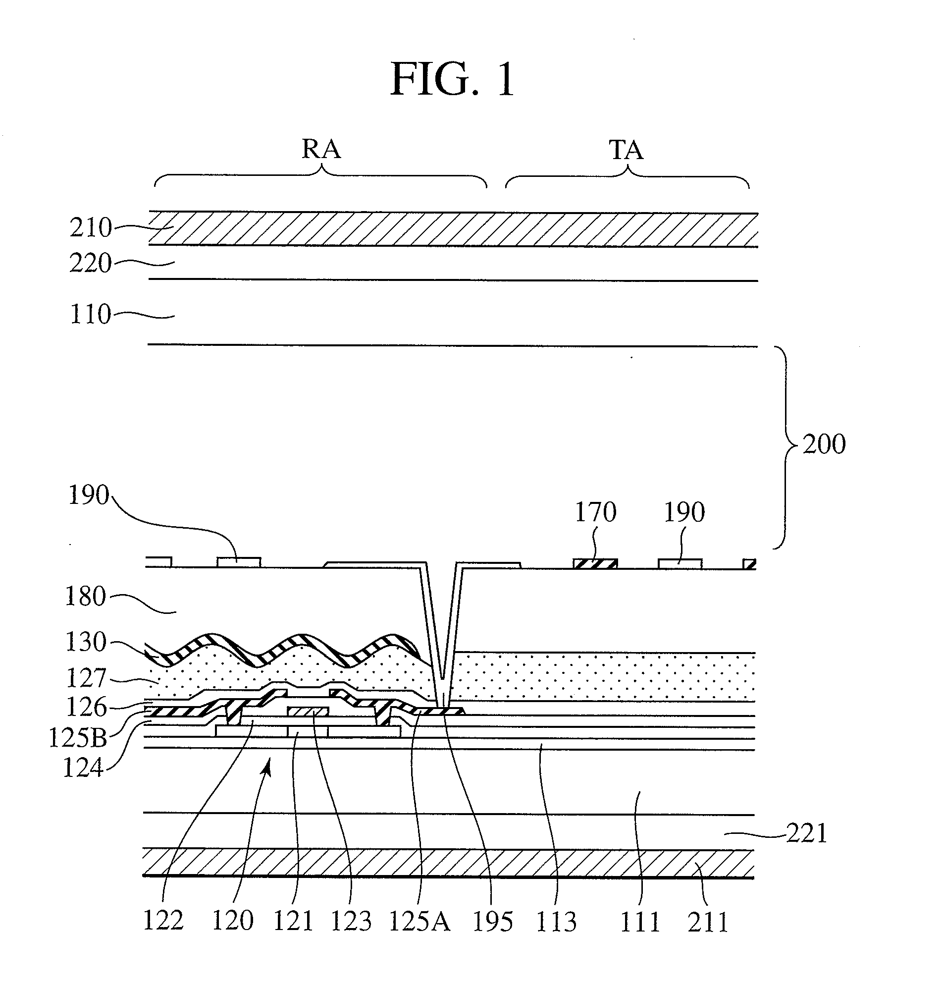
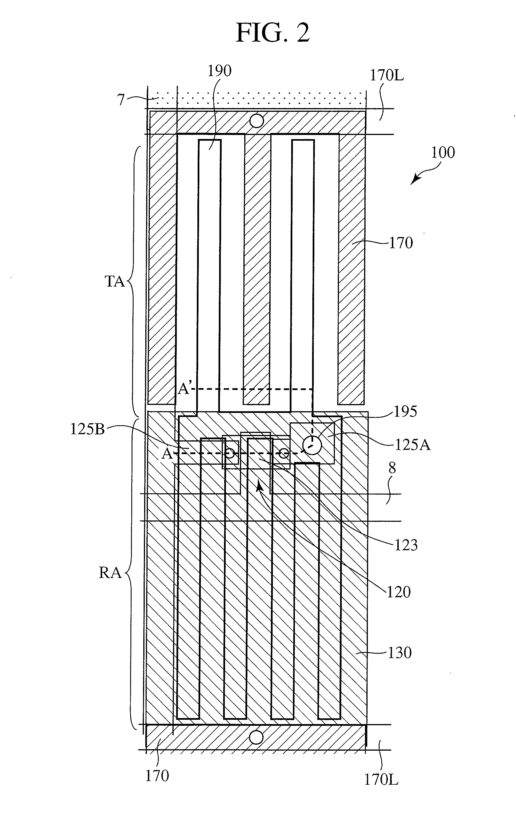
[0043]FIG. 1 is a cross-sectional view showing a schematic configuration of an essential section of a subpixel 100 in a liquid crystal display panel which forms part of a transflective liquid crystal display panel according to the present invention. Also, FIG. 2 is a plan view showing the schematic configuration of the essential section of the subpixel 100 in the liquid crystal display panel according to the present invention. FIG. 1 schematically illustrates a structure of section A-A′ of FIG. 2. FIG. 3 is a block diagram showing schematically an example of layout of the entire transflective liquid crystal display panel 1 according to the present invention.

[0044]Referring first to FIG. 3, the liquid crystal display panel 1 has a display area 2 in an area including a central portion of a second transparent substrate 111. A data driver circuit 3 that outputs image signals to data lines (signal lines) 7 is disposed above the display area 2, located to the left of which is a scanning d...

second embodiment

[0117]A multi-domain structure of a liquid crystal display panel using an isotropic liquid crystal will be next described.

[0118]Uniaxial, optically anisotropic media has the angle dependence of retardation. For this reason, there are azimuthal angles at which, even when bright display is created in a white state in the direction normal to the liquid crystal display apparatus, an increase in retardation causes display to look yellow, or a decrease in retardation causes display to look blue. As shown in FIG. 2, therefore, if the pixel electrode or common electrode in one pixel has comb teeth oriented in one direction, slight coloring will occur according to the particular viewing direction. To improve this viewing-angle characteristic, it is effective to take measures so that when an electric field is formed in the liquid crystal layer, birefringence will be induced in a plurality of directions. When regions different in the induction direction of the birefringence are formed in one p...

third embodiment

[0123]Yet another embodiment of the present invention is next described. FIG. 7 is a cross-sectional view showing a schematic configuration of an essential section of a subpixel in a liquid crystal display panel which forms part of a transflective liquid crystal display apparatus of the present invention. The liquid crystal display panel of the present invention is a modification of the display panel with the electrode structure of the transmission area TA in the foregoing embodiment described referring to FIG. 1. For this reason, elements with the same functions of the transflective liquid crystal display panel described in the foregoing embodiment are each assigned the same reference number or symbol, and repeated description of these elements is omitted.

[0124]In the present embodiment, a reflection area RA, as in the foregoing embodiment, includes a planarly formed common reflective electrode layer 130 and a comb-shaped pixel electrode 190 formed thereabove via insulation layers ...


PUM

PropertyMeasurementUnit
thicknessaaaaaaaaaa
thicknessaaaaaaaaaa
sizeaaaaaaaaaa

Abstract

This invention provides a transflective liquid crystal display apparatus using an isotropic liquid crystal applicable to various pixel sizes.
A liquid crystal display panel including a first transparent substrate 110, a second transparent substrate 111, and an isotropic liquid crystal layer 200 held in a sandwiched condition between the substrates, further has pixel electrodes 190 and common electrodes 130, 170 on the second transparent substrate 111, and includes a reflection area RA and a transmission area TA in one pixel. In the reflection area RA, the pixel electrode 190 is formed into a comb shape and the common electrode 130 is formed into a planar shape via an insulation layer 180. In the transmission area TA, the pixel electrode 190 and the common electrode 170 are formed into a comb shape on the same layer. An electric field formed in the liquid crystal layer 200 according to a particular voltage difference between the pixel electrode 190 and the common electrode 130, 170 will be weaker in the reflection area RA than in the transmission area TA.

Description

BACKGROUND OF THE INVENTION[0001]1. Field of the Invention[0002]The present invention relates generally to liquid crystal display apparatus that uses an optically isotropic liquid crystal material, and more particularly to a transflective type of liquid crystal display apparatus.[0003]2. Description of the Related Art[0004]Display apparatus is a medium that visually conveys information to humans, and in the modern age with an advanced information society, the display apparatus is an entity important to humans and society. In recent years, liquid crystal display apparatus, in particular, has significantly improved in performance, and is adopted as display devices for a variety of products from hand-held telephones to personal computers and even to large-screen televisions and the like. Liquid crystal displays generally comprise a liquid crystal display panel and a backlight (illuminating device) disposed on the rear face of the liquid crystal display panel in order to irradiate this ...

Claims


Application Information

Patent Timeline
Patent Type & Authority Applications(United States)
IPC IPC(8): G02F1/13363
CPCG02F1/133555G02F1/134363G02F2413/09G02F2001/133541G02F1/13718G02F1/133541G02F1/133631
Inventor ADACHI, MASAYATAKEDA, SHINTARO
Owner PANASONIC LIQUID CRYSTAL DISPLAY CO LTD
Why Eureka
Try Eureka