Light guide member, planar light source device using the light guide member, and display apparatus

Inactive Publication Date: 2009-11-19
SHOWA DENKO KK
View PDF4 Cites 41 Cited by
  • Summary
  • Abstract
  • Description
  • Claims
  • Application Information

AI Technical Summary

Benefits of technology

[0047]According to a light guide member related to the present invention, since a light irradiated upward from an illuminant can be reflected in a horizontal direction by a reflecting face in a cut portion, an amount of transmitted lights from the upper face of the cut portion can be reduced. As a result, the light guide plate related to the present invention can contribute to a uniformity in the total luminance and chromaticity in the case in which the light guide member is used for a planar light source device or the like.
[0048]Moreover, according to a planar light source device using such a light guide member, since a luminance at the section directly over an illuminant is reduced, a marked gap of a conspicuously luminescent spot or a chromaticity can be prevented.
[0049]Since the light guide member is configured by a plurality of divided members, it is easy to accommodate to the device with a larger size. Furthermore, a maintenance property is excellent in the case in which one or some divided members are damaged.
[0050]Here, according to the configuration in which the divided member is provided with a light diffusion portion at a facing plane, since a light reflected in a horizontal direction by an inclined face passes t

Problems solved by technology

However, such an edge light type display apparatus has a limitation in improving a luminance and a uniformity in the luminance, and it is difficult to meet the requirement of an enlargement of a display screen.
In addition, there are problems that color reproducibility and a response for the cold cathode tube 102 is not satisfactory, and that an after-image phenomenon occurs.
However, even in such a case, there is a problem that a luminance of the section dire

Method used


Image

  • Light guide member, planar light source device using the light guide member, and display apparatus
  • Light guide member, planar light source device using the light guide member, and display apparatus
  • Light guide member, planar light source device using the light guide member, and display apparatus

Examples


first embodiment

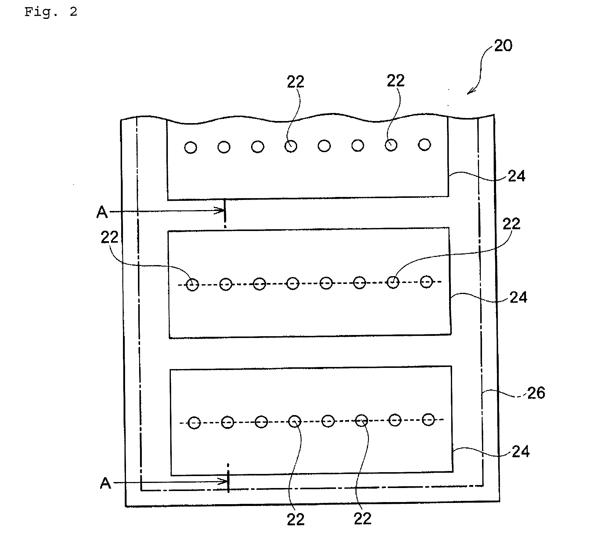
[0077]FIG. 2 is a schematic view showing a light guide member and a planar light source device adopting the light guide member related to the present invention, and FIG. 3 is a partially enlarged schematic cross sectional view along the A-A line of FIG. 2.

[0078]A planar light source device 20 is suitably used as a back light for a large size liquid crystal display in an almost rectangular shape for instance.

[0079]In the present description, as a matter of convenience for an explanation, one major face of the light guide member 26 means the bottom face of the light guide member 26, and the other major face of the light guide member 26 means the upper face of the light guide member 26.

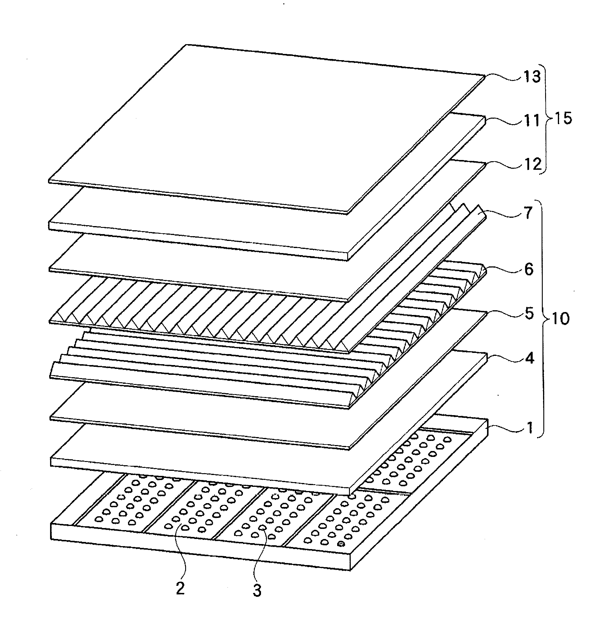
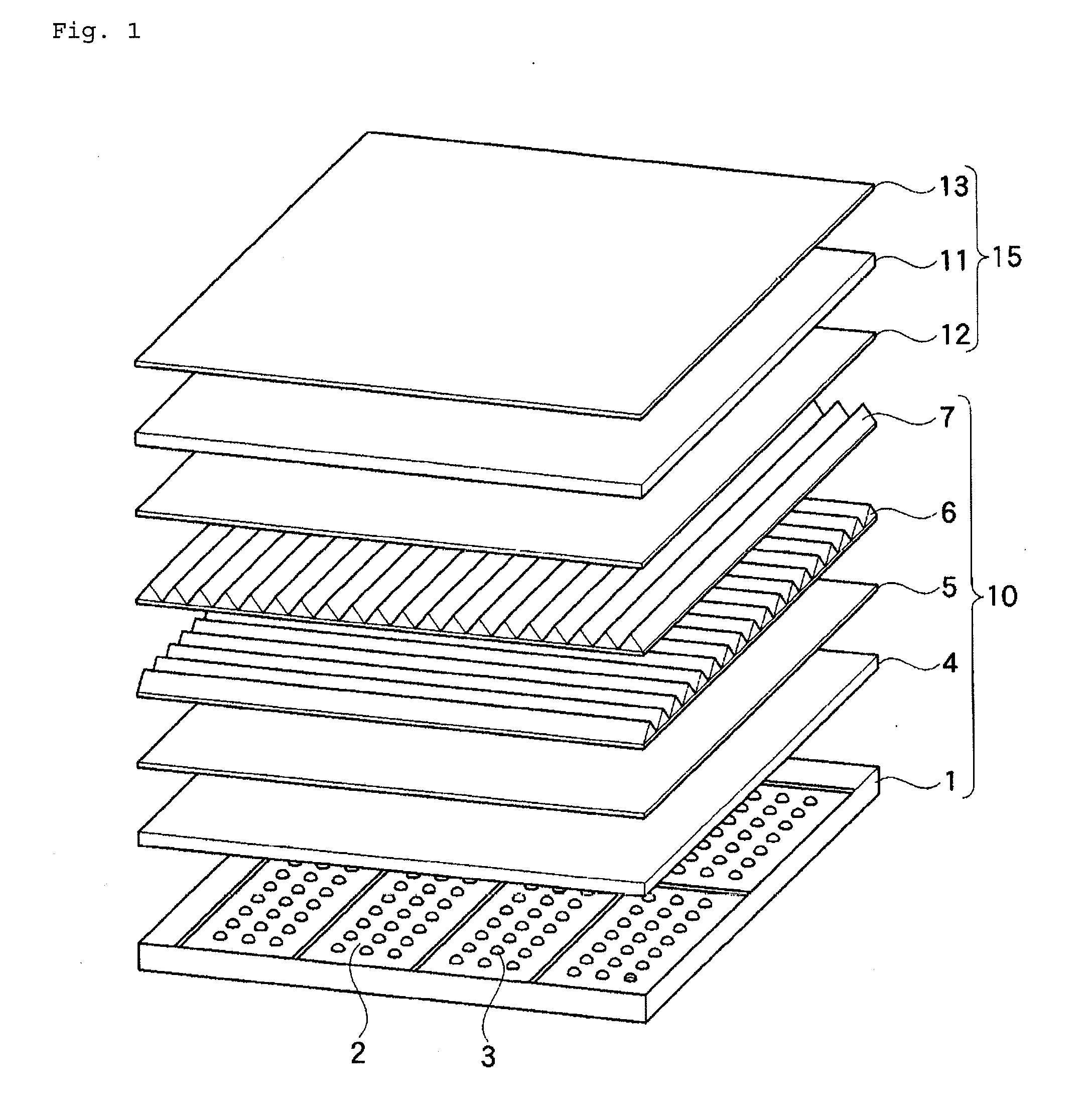
[0080]As shown in FIG. 2, a planar light source device 20 is provided with a plurality of light emitting diodes (LEDs) 22 which are illuminants, a substrate 24 on which the light emitting diodes 22 are disposed at a specified pitch, and a light guide member 26 disposed in such a manner that the light gui...

second embodiment

[0105]FIG. 6 is a schematic plan view showing a light guide member and a planar light source device adopting the light guide member related to the present invention, and FIG. 8 is a partially enlarged schematic cross sectional view along the B-B line of FIG. 6.

[0106]A planar light source device 60 provided with the light guide member is suitably used as a back light for a large size liquid crystal display in an almost rectangular shape for instance.

[0107]The planar light source device 60 is provided with a chassis 62 in an almost rectangular shape, a plurality of substrates 66 on which the LED lamps 64 in which a plurality of LED devices with different luminance colors (a red LED, a green LED, and a blue LED) are put together as one lamp that is an illuminant are disposed at a specified pitch, and a plurality of divided members 68 of a light guide member (plate) disposed in such a manner that the light guide member covers the area over the substrates 66.

[0108]While a plurality of LE...

third embodiment

[0135]FIG. 10 is a schematic plan view showing a light guide member and a planar light source device adopting the light guide member related to the present invention, and FIG. 12 is a partially enlarged schematic cross sectional view along the C-C line of FIG. 10. In the description of the present embodiment, “upward”, “downward”, “left”, and “right” are used as a matter of convenience for an explanation. For instance, a direction of a divided member 88 viewed from an LED lamp 84 is “upward” in FIG. 12. In addition, a direction of one edge portion 88a is “right”, and a direction of the other edge portion 88b is “left” in FIG. 11.

[0136]A planar light source device 80 provided with the light guide member is suitably used as a back light for a large size liquid crystal display in an almost rectangular shape for instance.

[0137]As shown in FIG. 10, the planar light source device 80 is provided with a chassis 82 in an almost rectangular shape, LED lamps 84 in which a plurality of LED devi...


PUM


Abstract

A light guide member in which a light that has entered one major face from an illuminant is emitted from the other major face, is characterized by comprising:
    • a cut portion provided with a specified face inclined toward the other face at a section of one major face that faces the illuminant, and
    • a reflecting portion, which reflects a light emitted from the illuminant, on the inclined face.

Description

CROSS REFERENCE TO RELATED APPLICATIONS[0001]This application is an application filed under 35 U.S.C. §111(a) claiming benefit pursuant to 35 U.S.C. §119(e) (1) of the filing date of Provisional Application Ser. Nos. 60 / 735,872 filed on Nov. 14, 2005, 60 / 752,892 filed on Dec. 23, 2005, and 60 / 797,775 filed on May 5, 2006 pursuant to 35 U.S.C. §111(b).TECHNICAL FIELD[0002]The present invention relates to a light guide member (plate), a planar light source device using the light guide member (plate), and a display apparatus that are used in the case in which an illuminant such as a light emitting diode is used as an illuminant of a back light for a liquid crystal.BACKGROUND ART[0003]Conventionally, the main stream of such a back light illuminant for a liquid crystal display has been the so-called edge light type in which a cold cathode tube is disposed on the edge face of the chassis (for instance, see the Patent Document 1).[0004]FIG. 14 illustrates a conventional back light illumina...

Claims


Application Information

Patent Timeline
IPC IPC(8): G02F1/13357F21S8/10H01L33/48
CPCG02B6/0018G02F1/133606G02F1/133603G02B6/0055G02B6/00G02B6/0001
Inventor GOMI, SHUJISHINOZAKI, KENJINAIJO, SHUICHIWATANABE, TAKEO
Owner SHOWA DENKO KK
Why Eureka
Try Eureka