Infrared room heater system

a technology of infrared room heater and heater body, which is applied in the field of energy-saving, safe, high-tech, in-wall building and room heaters, can solve the problems of inefficiency, inefficiency, and inefficient heaters, and achieve the effect of avoiding fire hazards and preventing excessive heat buildup

Inactive Publication Date: 2009-11-19
ACEPOWER LOGISTICS
View PDF54 Cites 14 Cited by
  • Summary
  • Abstract
  • Description
  • Claims
  • Application Information

AI Technical Summary

Benefits of technology

[0012]It is still another object of this invention to provide such a heater that includes effective heat shielding to prevent excessive build up of heat in any wall into which it may be installed, thereby avoiding a fire hazard.
[0013]It is a further object of this invention to provide for the user easy access, maintenance and cleaning of internal components thereof, which components include a removable heat exchanger assembly and a mesh, electrostatic air filter.

Problems solved by technology

In-the-wall room heaters have mainly comprised apparatus for delivering centrally heated air ducted from an electrical or gas central heater, of an inefficient nature, located outside the building or in a cellar, furnace room or garage.
Heating and maintenance costs for such heaters have run unacceptably high.
Each of these kinds of heaters is relatively noisy, inefficient, expensive to operate and, in the case of propane and kerosene wall-mounted heaters, also consume room oxygen to the potential detriment of the health of room occupants.
Portable room heaters have been constructed similarly to the above-mentioned stationary room heaters and have also been relatively inefficient to run, sometimes have been fire prone, and consume room oxygen.

Method used


Image

  • Infrared room heater system
  • Infrared room heater system
  • Infrared room heater system

Examples


Embodiment Construction

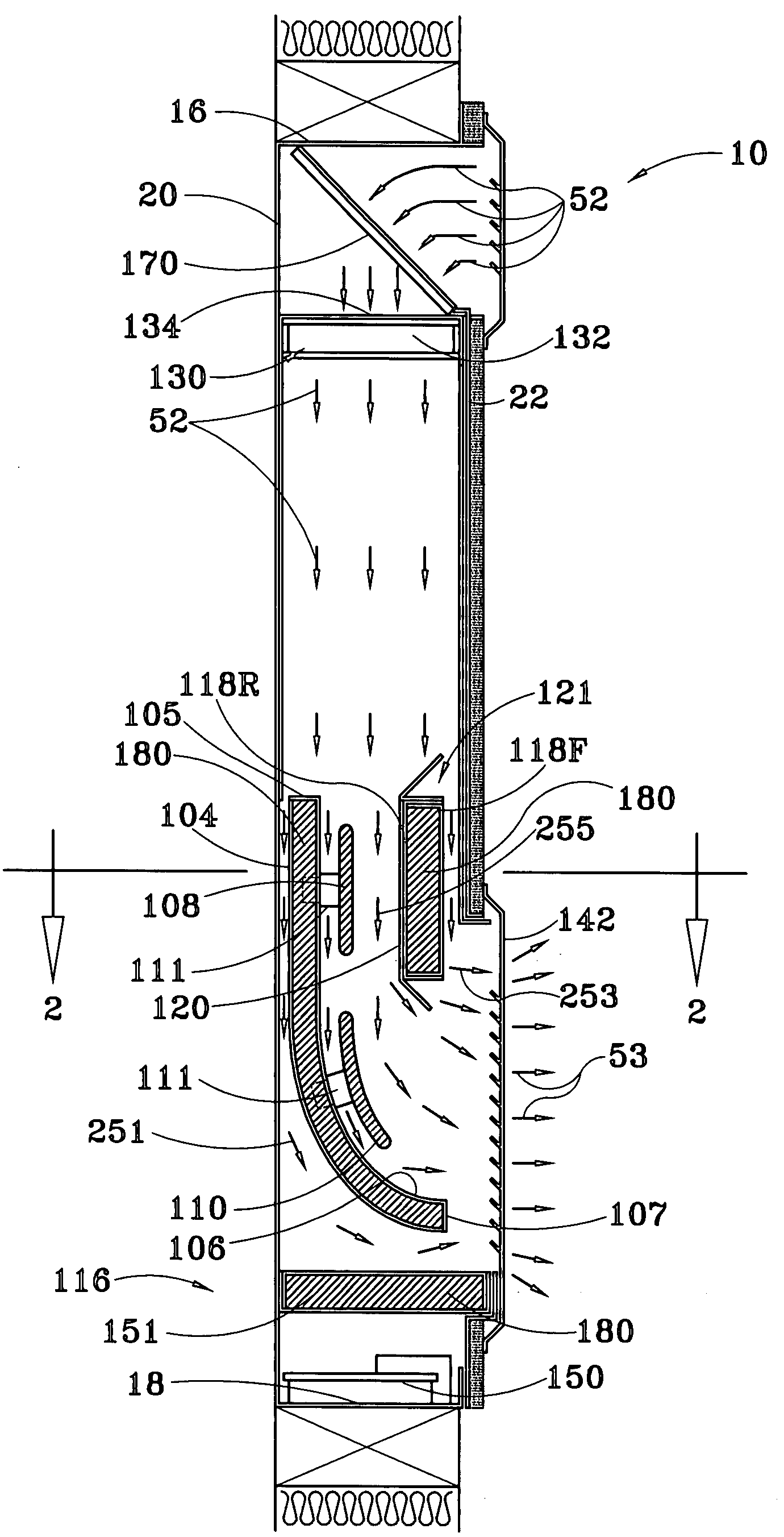
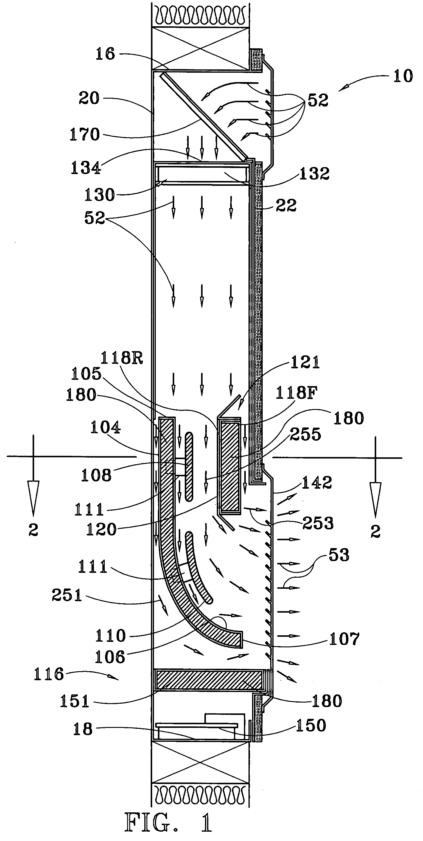
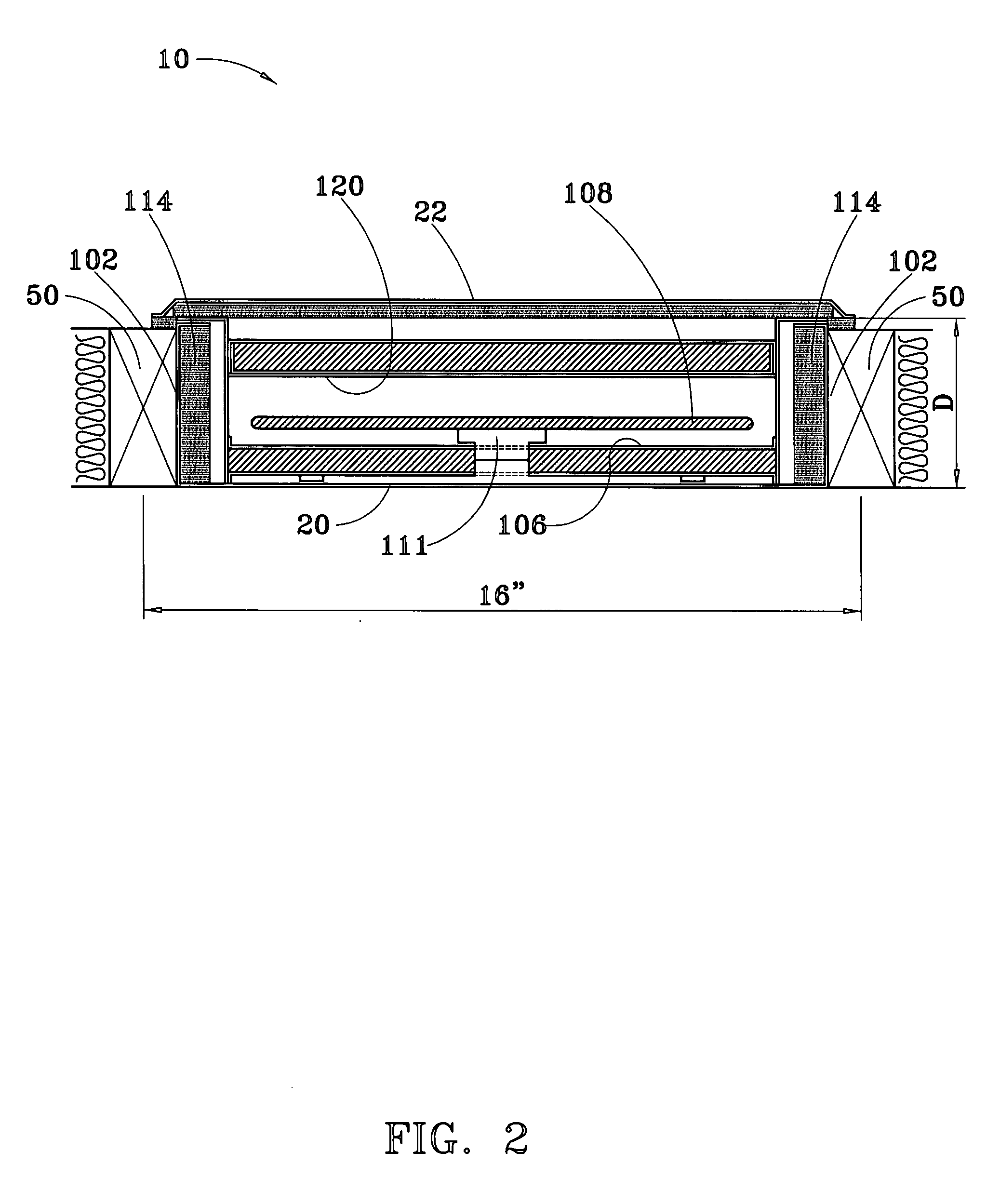
[0035]Referring to FIGS. 1 and 2, a preferred embodiment of an electrically-powered, infrared heater system of the present invention, denoted generally by the numeral 10, is depicted in vertical and horizontal cross-sectional views, respectively, installed between wall studs 50 spaced 16 inches (40.6 cm) apart within a standard interior building wall having depth D of 3½ inches (8.9 cm). As denoted by the arrows 52, when the system is in an operating heating mode, room air is drawn into the interior of the system 10 through an air child-proof, air inlet grate 140, thence through an electrostatic mesh filter 170 by rotating blades of electric fans 132, and then forced downward through a removable heat exchanger assembly 100 where the air is heated and from whence the heated air, denoted by arrows 53, exits through a child-proof, air outlet grate 142 back into the room.

[0036]As may best be seen in FIG. 6, the system 10 includes a housing, denoted generally by the numeral 12, having a ...


PUM


Abstract

An infrared, room heater system for installation in a wall or on a floor An electric fan assembly draws room air into a housing, through three parallel, air transit channels where the air is heated by infrared radiation within and about a heat exchanger assembly, and thence back out into the room One or more ceramic heating elements attached to a copper plate incorporate a resistive conductor that causes the elements to emit infrared radiation when electrically energized The first copper plate lies adjacent to, but spaced away from, a first heat insulated housing sidewall, thereby defining a first air transit channel The second air transit channel is defined by the space between the second copper plate and the second housing sidewall, and the third air transit channel is defined by the space between the two copper plates.

Description

CROSS REFERENCE TO RELATED APPLICATIONS[0001]This application claims the benefit of a provisional patent applications by the same applicants for a first embodiment of the same invention filed on Nov. 1, 2006, application No. 60 / 855,661 and a provisional application by the same applicants for a second embodiment of the same invention filed on Jan. 8, 2007, application No. 60 / 879,084.STATEMENT REGARDING GOVERNMENT SPONSORED RESEARCH[0002]None.BACKGROUND OF THE INVENTION[0003]1. Field of the Invention[0004]This invention relates generally to energy efficient, safe, high tech, in-the-wall building and room heaters that are intended to promote personal comfort and health, and particularly to such heaters that are electrically powered and emit infrared radiation. In a first embodiment, the invention can be unobtrusively installed within the confines of a standard interior wall space that is at least 3½ inches (8.9 cm) deep and between two 16 inch (40.6 cm) on center (or more) wall studs. ...

Claims


Application Information

Patent Timeline
Patent Type & Authority Applications(United States)
IPC IPC(8): F24H3/12F24H3/00H05B1/02
CPCF24H3/0417
Inventor SEARLE, BRUCE R.ANDERSON, ALEXANDER
Owner ACEPOWER LOGISTICS
Why Eureka
Try Eureka