Motor and fan apparatus having the motor
- Summary
- Abstract
- Description
- Claims
- Application Information
AI Technical Summary
Benefits of technology
Problems solved by technology
Method used
Image

Examples
first preferred embodiment
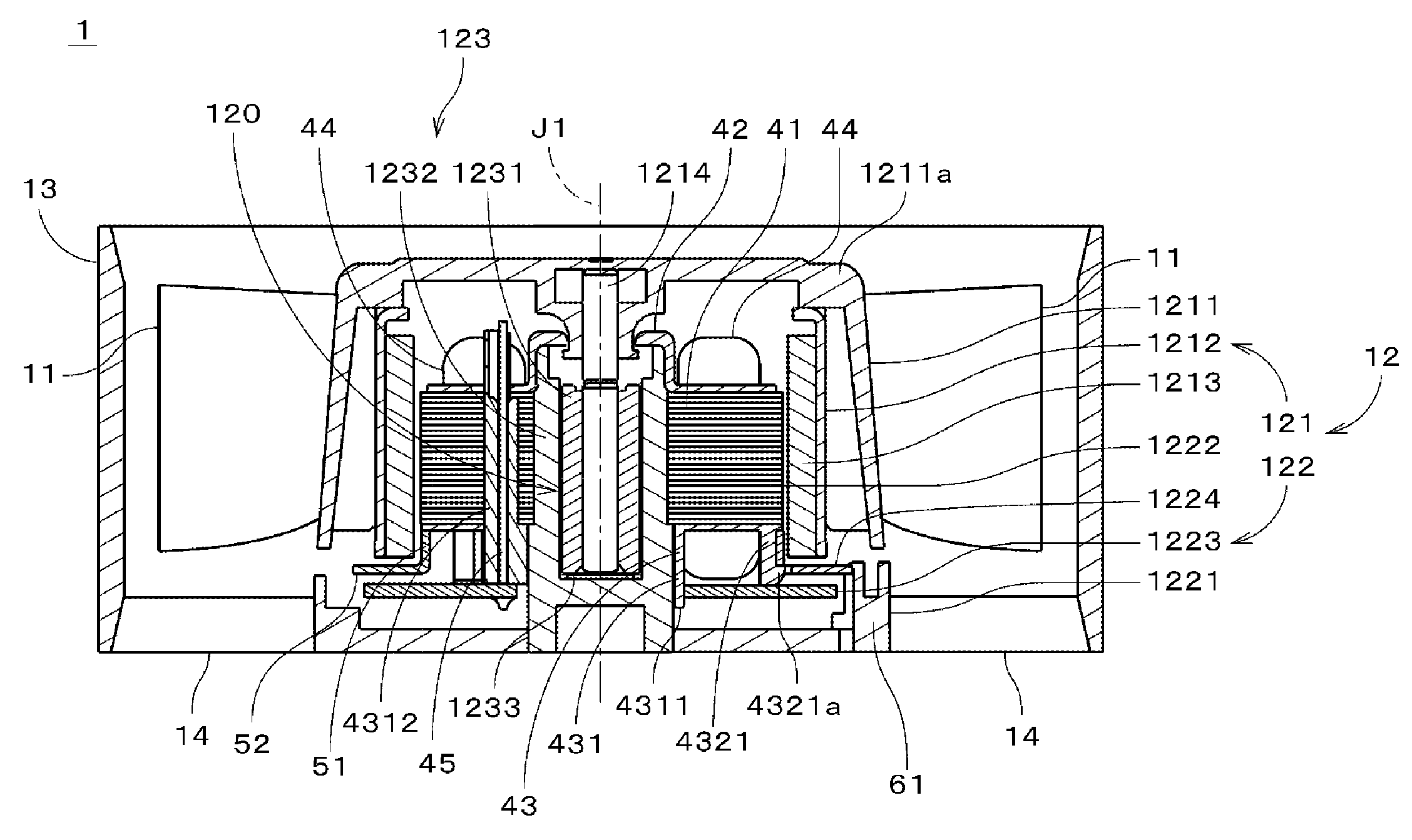
[0050]FIG. 1 is a longitudinal sectional view of an axial fan 1 which is a fan apparatus according to the first preferred embodiment of the present invention. The axial fan 1 has a motor 12 (for example, an electric single phase motor), a plurality of blades 11, a housing 13 surrounding the motor 12, and a plurality of supporting ribs 14. The housing 13 is connected to the motor 12 through the supporting ribs 14. The plurality of blades 11 are fixed to a rotor portion 121 of the motor 12 such that the plurality of supporting ribs 14 are arranged to support the motor 12.
[0051]The housing 13 and the supporting ribs 14 are preferably formed as a single member by, for example, injection molding with a resin or plastic. Alternatively, the housing 13 and the supporting ribs 14 may also be formed as a single member through aluminum die-casting. In FIG. 1, the outlines of the blades 11 and the supporting ribs 14 are shown on the right and left sides of the center axis J1 for convenience of ...
second preferred embodiment
[0105]FIG. 19 is a perspective view showing a stator 1222, a magnetic member 1224a, and a printed wiring board 1223 of an axial fan according to the second preferred embodiment. FIG. 20 is a perspective view of the stator 1222. In FIGS. 19 and 20, the shape of an upper insulator 42 of the stator 1222 is drawn simply.
[0106]As shown in FIG. 19 pairs of lug portions 523 are preferably provided at four positions in the circumferential direction in the outer circumference of the flat portion 52 at regular intervals in the magnetic member 1224a. The holes 53 shown in FIG. 4 are omitted in the magnetic member 1224a. One notch 521 is defined in the flat portion 52, and a portion of a lower end portion of the cylindrical portion 51 is cut out at the position where the notch 521 is provided. The rest of the magnetic member 1224a is the same as that of the magnetic member 1224, and the same reference signs are given to the same constituent elements.
[0107]As shown in FIG. 20, plate-shaped protr...
third preferred embodiment
[0119]FIG. 23 is a plan view showing a magnetic member 1224b in an axial fan according to the third preferred embodiment. In the magnetic member 1224b, the holes 53 of the magnetic member 1224 shown in FIG. 4 are omitted. An upper portion of a cylindrical portion 51 in FIG. 23 is cut out, and a portion of a flat portion 52 projects inwardly in the radial direction. In the following description, the portion of the flat portion 52 is referred to as a “projected portion 54”. On the opposite side of the projected portion 54 in the circumferential direction, i.e., on the lower side of FIG. 23, a slit 55 extending across the magnetic member 1224b in the radial direction is provided. The rest of the magnetic member 1224b is almost the same as that of the magnetic member 1224.
[0120]FIG. 24 is a bottom view of a lower insulator 43b. Protrusions 71 are provided in tooth covering portions 432 which are located on the left, right, and lower side of FIG. 24. In a tooth covering portion 432 locat...
PUM
 Abstract
Description
Claims
Application Information
 - R&D
- Intellectual Property
- Life Sciences
- Materials
- Tech Scout
- Unparalleled Data Quality
- Higher Quality Content
- 60% Fewer Hallucinations
Browse by: Latest US Patents, China's latest patents, Technical Efficacy Thesaurus, Application Domain, Technology Topic, Popular Technical Reports.
© 2025 PatSnap. All rights reserved.Legal|Privacy policy|Modern Slavery Act Transparency Statement|Sitemap|About US| Contact US: help@patsnap.com