Floating gastrointestinal anchor

a floating, gastrointestinal technology, applied in the field of gastrointestinal apparatus implantation, can solve problems such as gastric emptying, achieve the effects of promoting satiety, slowing gastric emptying, and enhancing satiety sensation

Active Publication Date: 2009-11-19
SPATZ FGLA INC (US)
View PDF70 Cites 149 Cited by
  • Summary
  • Abstract
  • Description
  • Claims
  • Application Information

AI Technical Summary

Benefits of technology

[0077]In some embodiments of the present invention, a floating gastrointestinal anchor comprises a flexible tube, which, in its relaxed position, is shaped so as to define a generally planar base portion, and a proximal portion that projects away from the plane defined by the base portion, typically in an approximately perpendicular direction. The anchor further comprises at least two cross-bar elements, the ends of which are positioned in a vicinity of the base portion of the anchor. The cross-bar elements help maintain the shape of the anchor. The anchor typically, but not necessarily, is positioned in an antrum, adjacent to the pyloric valve, and to some extent interferes with natural antral contractions, thereby slowing gastric emptying and enhancing the sensation of satiety. The proximal portion of the anchor is typically, but not necessarily, coupled to a device, such as a therapeutic device, e.g., a balloon.
[0078]Typically, each of the cross-bar elements is shaped so as to define a lumen therethrough, and comprises an elastic coupling band that passes through the lumen. Two portions of each of the coupling bands protrude from the cross-bar element, and are coupled to the base portion of the anchor at two respective points that are approximately opposite one another. In order to enable transesophageal insertion of the anchor using a gastroscope, the anchor is typically stretched until it assumes an elongated position, in which the tube thereof is generally straight. The elastic coupling bands of the cross-bar elements enable the anchor to assume this elongated position, in which the cross-bar elements are displaced from their relaxed positions until they are approximately parallel with the tube of the anchor. A generally stiff rod is inserted into a lumen of the tube, in order to maintain the stretched position during insertion. Once the anchor has been appropriately positioned in the stomach, the rod is removed, allowing the anchor to assume its relaxed position.
[0079]As will be appreciated by those persons skilled in the art, a feature provided by some embodiments of the present invention is the ease in which an anchor may be inserted into the gastrointestinal system. Another feature provided by some embodiments of the present invention is the safety and security provided by the use of such an anchor. It is therefore an object of some embodiments of the present invention to provide a safe and easy method of inserting and securing a floating anchor into the gastrointestinal system so that a variety of devices may be safely secured therein. It is another object of sonic embodiments of the present invention to safely and securely anchor a balloon in the stomach for promoting a feeling of satiety in a subject. Additional objects of embodiments of the present invention will become apparent from the following description.
[0134]In an embodiment, the apparatus includes a closure mechanism coupled to a proximal end of the inflation tube, configured to maintain pressure within the balloon by preventing leakage of fluid therefrom into the stomach of the subject.

Problems solved by technology

The anchor typically, but not necessarily, is positioned in an antrum, adjacent to the pyloric valve, and to some extent interferes with natural antral contractions, thereby slowing gastric emptying and enhancing the sensation of satiety.

Method used


Image

  • Floating gastrointestinal anchor
  • Floating gastrointestinal anchor
  • Floating gastrointestinal anchor

Examples


Embodiment Construction

[0172]The following preferred embodiments as exemplified by the drawings are illustrative of embodiments of the invention, and are not intended to limit the invention as encompassed by the claims of this invention.

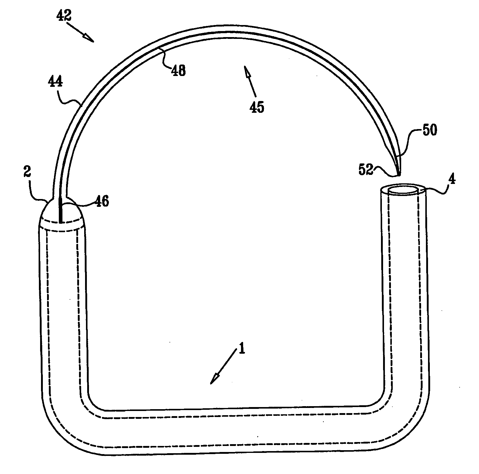
[0173]A floating gastrointestinal anchor 1, as generally illustrated in the figures, is provided for securing devices in the gastrointestinal tract. The gastrointestinal tract, as used herein, includes the esophagus. Although devices and methods are described in some embodiments as being useful for anchoring an inflated balloon in the stomach for affecting weight loss, it is to be understood that the methods and devices described herein can be used for securing any device for its intended purpose anywhere in the gastrointestinal tract.

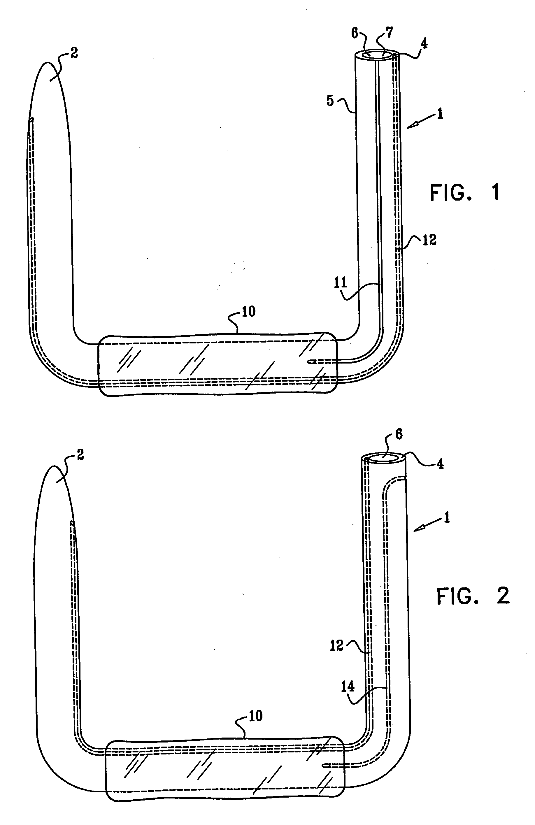
[0174]FIG. 1 depicts floating gastrointestinal anchor 1, in accordance with an embodiment of the present invention. As shown in the embodiment of FIG. 1, anchor 1 has a generally “C” or “U” shape. The anchor has a distal end 2, a proximal end...


PUM


Abstract

Apparatus (90) is provided for use in a stomach of a subject. The apparatus includes a balloon (92), adapted for placement in the stomach, and all anchor (102), coupled to the balloon. The anchor is adapted to prevent the balloon from passing into a duodenum of the subject. The apparatus further includes an inflation tube (96), coupled to the balloon to permit inflation of the balloon, and is adapted to stretch from the stomach to a mouth of the subject to facilitate inflation of the balloon. Other embodiments are also described.

Description

CROSS-REFERENCES TO RELATED APPLICATIONS[0001]The present application:[0002](a) claims priority flow:[0003]U.S. Provisional Patent Application 60 / 787,124 to Brooks, filed Mar. 28, 2006, entitled, “Floating gastrointestinal anchor”; and[0004]U.S. Provisional Patent Application 60 / 815,624 to Brooks, filed Jun. 21, 2006, entitled, “Floating gastrointestinal anchor”; and[0005](b) is related to:[0006]a US patent application to Brooks, filed on even date herewith, entitled, “Floating gastrointestinal anchor.”[0007]Each of the above applications is assigned to the assignee of the present invention and is incorporated herein by reference.FIELD OF THE INVENTION[0008]The present invention generally relates to inplantable medical apparatus. Specifically, the present invention relates to apparatus for implantation in the gastrointestinal tract.BACKGROUND OF THE INVENTION[0009]Morbid obesity remains an ever-growing problem in the U.S. Varying forms of gastric bypass surgery have developed and ha...

Claims


Application Information

Patent Timeline
Patent Type & Authority Applications(United States)
IPC IPC(8): A61B17/08A61M29/00
CPCA61F5/0036A61F5/003A61F5/0089
Inventor BROOKS, JEFFREY S.HIRSZOWICZ, ERAN
Owner SPATZ FGLA INC (US)
Why Eureka
Try Eureka