Fuel injection valve

a technology of fuel injection valve and internal combustion engine, which is applied in the direction of fuel injection apparatus, spraying apparatus, feeding system, etc., can solve the problems of large increase in the number of components and processes, inability to accurately control the amount of fuel injection, and travel members to bounce, so as to achieve constant distance between the armature and the cor

Active Publication Date: 2009-11-26
MITSUBISHI ELECTRIC CORP
View PDF8 Cites 33 Cited by
  • Summary
  • Abstract
  • Description
  • Claims
  • Application Information

AI Technical Summary

Benefits of technology

[0011]A fuel injection valve according to the present invention has been implemented in order to solve the foregoing problems; the objective thereof is to provide a fuel injection valve, in which, without increasing the number of components and the number of processes, bouncing of the

Problems solved by technology

The vertical movement causes the armature 7 to collide with the core 4 or causes the needle 8 to collide with the valve seat 15; as a result, in some cases, the impact of the collision causes the travel members to bounce, whereby the amount of fuel injection cannot accurately be controlled.
However, there has been a problem that the number of components and the number of processes considerably increase in such a structure, as disclosed in National Publication of International Patent Application No. 2002-506502, in which the armature 7 and the needle 8 are coupled with each other by mean

Method used


Image

  • Fuel injection valve
  • Fuel injection valve
  • Fuel injection valve

Examples


embodiment 1

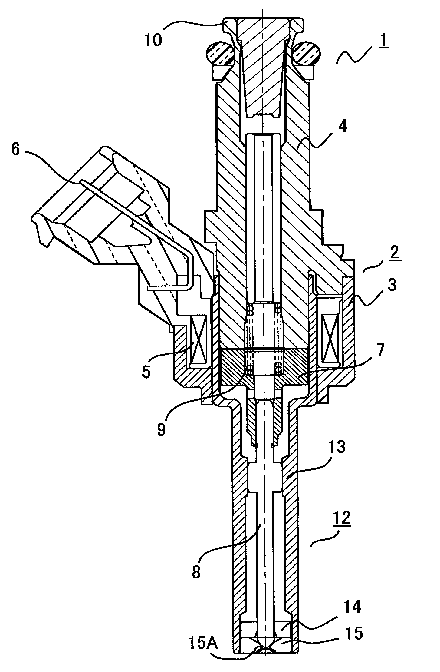
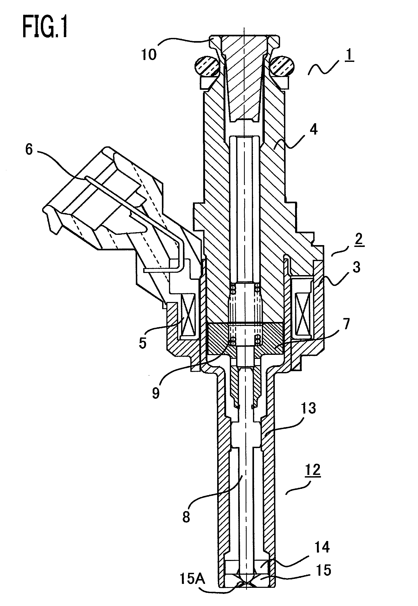
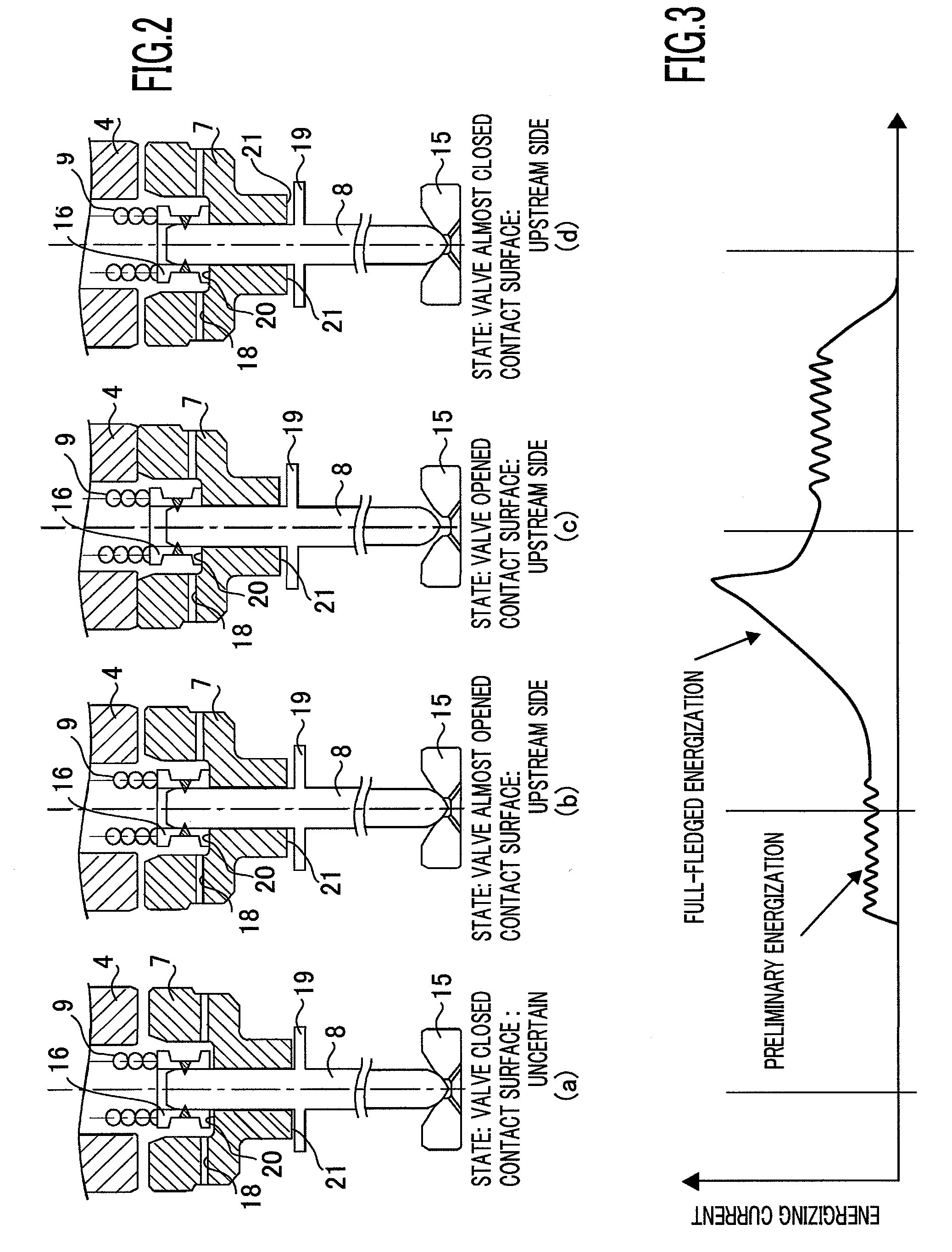
[0021]Embodiment 1 of the present invention will be explained below. The configuration of a fuel injection valve 1 according to the present invention is the same in appearance as that illustrated in FIG. 6; therefore, Embodiment 1 will be explained with reference to FIG. 6. In FIG. 6, a stepped portion 19 is provided on the side surface of a needle 8, an armature 7 is put on the upstream side of the stepped portion 19 in such a way as to be penetrated by the needle 8, and the front end of the needle 8 is fixed in a stopper 16 by means of welding or the like in such a way that a stopper 16 and the stepped portion 19 flank the armature 7; on that occasion, the front end of the needle 8 is press-fitted and welded in the stopper 16, while the stopper 16 is adjusted in such a way that the armature 7 can travel by a predetermined amount with respect to the needle 8. Additionally, by making a valve-closing spring 9 make contact with the top end of the stopper 16, the armature 7 and, eventu...


PUM


Abstract

The objective of the present invention is to realize the structure, of a fuel injection valve, in which bouncing of the needle can be suppressed and the armature position can be fixed while the valve is closed, without increasing the number of components and the number of processes. In a fuel injection valve including an armature that is repelled or attracted by a core, by de-energizing or energizing a coil; a needle that opens or closes a valve seat in accordance with a reciprocal travel of the armature; and a valve-closing spring that biases the needle so as to close the valve, when the coil is de-energized, the needle and the armature are fixed in such a way that the armature can travel in an axis direction by a predetermined amount with respect to the needle, and the coil is preliminarily energized while the fuel injection valve is closed by the needle.

Description

BACKGROUND OF THE INVENTION[0001]1. Field of the Invention[0002]The present invention relates to a fuel injection valve for an internal combustion engine and particularly to improvement of an electromagnetic fuel injection valve utilized in a fuel supply system in an internal combustion engine.[0003]2. Description of the Related Art[0004]The typical configuration of a fuel injection valve of this kind will be explained with reference to FIG. 1. As illustrated in FIG. 1, a fuel injection valve 1 is configured mainly with a solenoid device 2 and a valve device 12. The solenoid device 2 is configured with a housing 3 that is a yoke portion of a magnetic circuit, a core 4 that is a fixed iron core portion of the magnetic circuit, a coil 5 energized from outside via a connector 6, an armature 7 that is a moving iron core portion of the magnetic circuit, and a valve-closing spring 9 that biases a needle 8 coupled with the armature 7 downstream. In addition, a fuel is supplied through a fu...

Claims


Application Information

Patent Timeline
IPC IPC(8): F02M51/06
CPCF02M51/061F02M2200/306F02M51/066
Inventor SHINGU, AKIOAOTA, MASAYUKIMUNEZANE, TSUYOSHI
Owner MITSUBISHI ELECTRIC CORP
Why Eureka
Try Eureka