

Single-phase motor and hermetic compressor
- Summary
- Abstract
- Description
- Claims
- Application Information
AI Technical Summary
Benefits of technology
Problems solved by technology
Method used
Image

Examples
embodiment 1
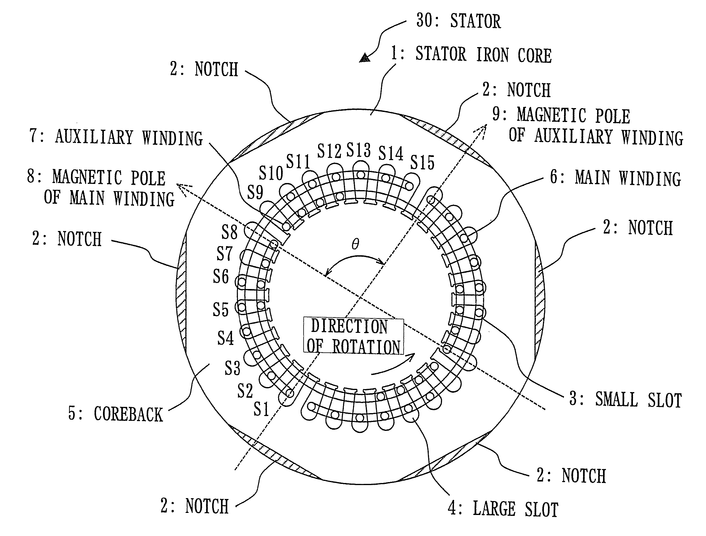
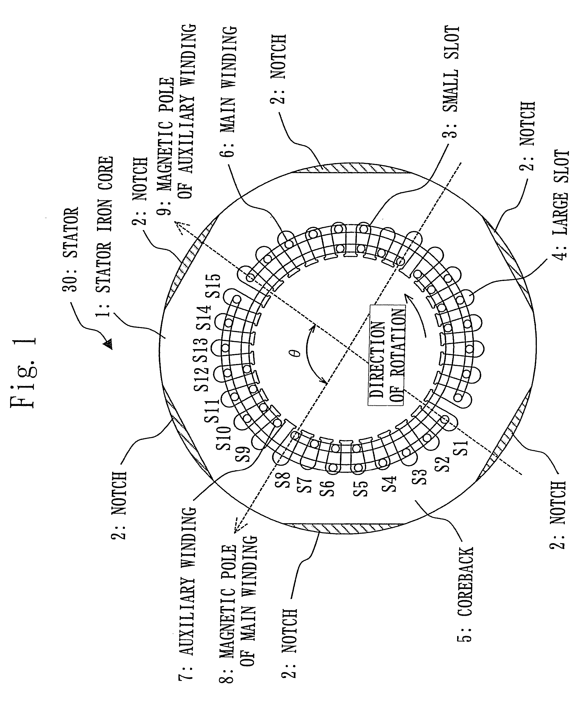
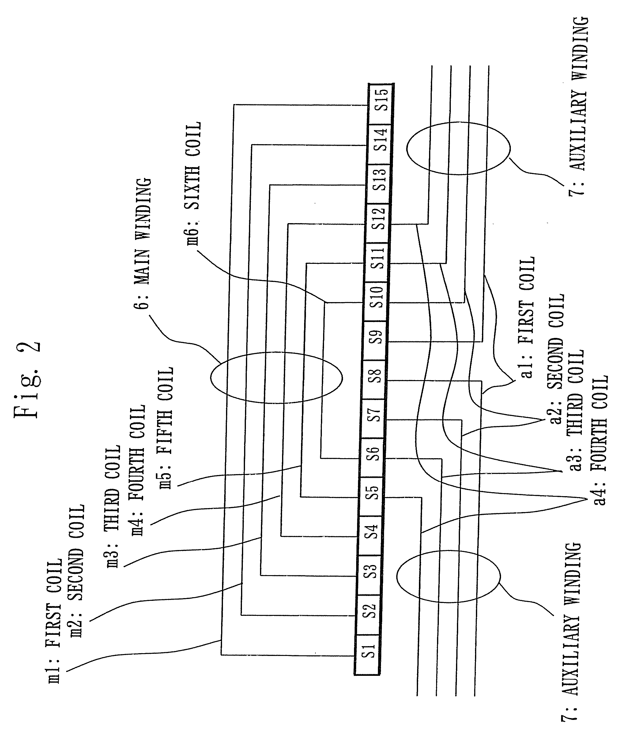
[0016]FIGS. 1 through 8 show the first embodiment. FIG. 1 is a horizontal cross sectional view showing a stator 30 of a single-phase motor; FIG. 2 is an arrangement view of a main winding 6 and an auxiliary winding 7 of concentric winding arrangement; FIG. 3 shows the number of windings including the main winding 6 and the auxiliary winding 7 to be inserted to slots having numbers S1 through S15 when the number of slots is 30; FIG. 4 shows an example of the number of windings including the main winding 6 and the auxiliary winding 7 to be inserted to slots having numbers S1 through S15 when the number of slots is 30; FIG. 5 shows the number of windings including the main winding 6 and the auxiliary winding 7 to be inserted to slots having numbers S1 through S13 when the number of slots is 26; FIG. 6 shows an example of the number of windings including the main winding 6 and the auxiliary winding 7 to be inserted to slots having numbers S 1 through S13 when the number of slots is 26; ...
embodiment 2
[0075]FIGS. 9 through 11 show the second embodiment: FIG. 9 is a horizontal cross sectional view showing a stator 40 of a single-phase motor; FIG. 10 is a horizontal cross sectional view of the stator 40 of a single-phase motor used for an induction motor 50 (an example of a single-phase motor); and FIG. 11 is a horizontal cross sectional view of the stator 40 of a single-phase motor used for a synchronous induction motor 60 (an example of a single-phase motor).
[0076]As shown in FIG. 9, two notches 2 located at an outer circumferential side of four consecutive small slots 3 among the notches 2 of FIG. 1 are made large so as to become large notches 21. At this time, a roughly straight lined part of the large notch 21 is moved to the center side of a stator iron core 1 so as to increase the area. A point that is different from FIG. 1 is only a part of the large notch 21.
[0077]The magnetic flux density of the coreback 5 located at the outer circumferential part of the small slot 3 is l...
embodiment 3
[0087]FIGS. 12 and 13 show the third embodiment: FIG. 12 shows torque characteristics in respect of the revolution of a single-phase induction motor 50; and FIG. 13 shows motor efficiency characteristics in respect of a magnetic pole angle of a single-phase induction motor 50.
[0088]In FIG. 10, the case has been explained, in which the magnetic pole angle θ of the main winding magnetic pole 8 in respect of the auxiliary winding magnetic pole 9 is 96 degrees (the dislocation of windings between the main winding 6 and the auxiliary winding 7 is 96 degrees in electrical angle). It is also possible to make the magnetic pole angle θ 84 degrees (corresponding to 7 slots out of total 30 slots) by dislocating the winding arrangement.
[0089]As shown in FIG. 12, it is found that the torque is increased in the case of 96 degrees compared with the case of the magnetic pole angle θ=84 degrees. That the torque is increased means that the revolution is increased in the case of 96 degrees under the c...
PUM
 Abstract
Description
Claims
Application Information