

RFID tag for structure
a technology of rfid tags and structures, applied in the direction of burglar alarms, mechanical actuation of burglar alarms, burglar alarms by hand-portable objects, etc., can solve the problems of accelerating concrete neutralization and concrete deformation, and achieve the effect of reducing the size of the tag and widening the rang
- Summary
- Abstract
- Description
- Claims
- Application Information
AI Technical Summary
Benefits of technology
Problems solved by technology
Method used
Image


Examples
first embodiment
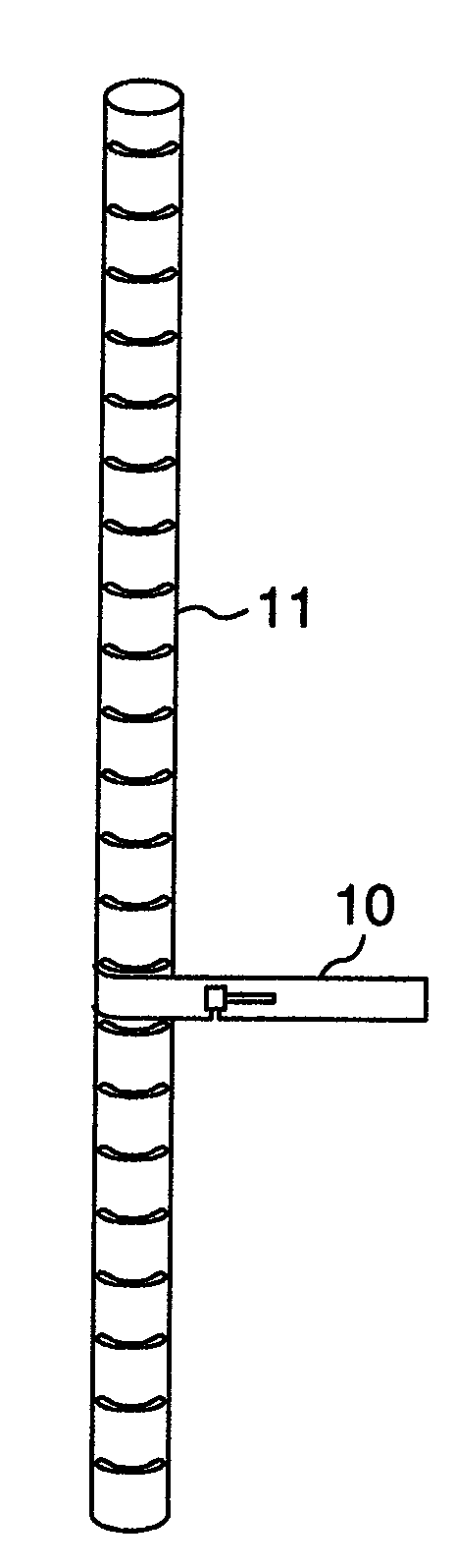
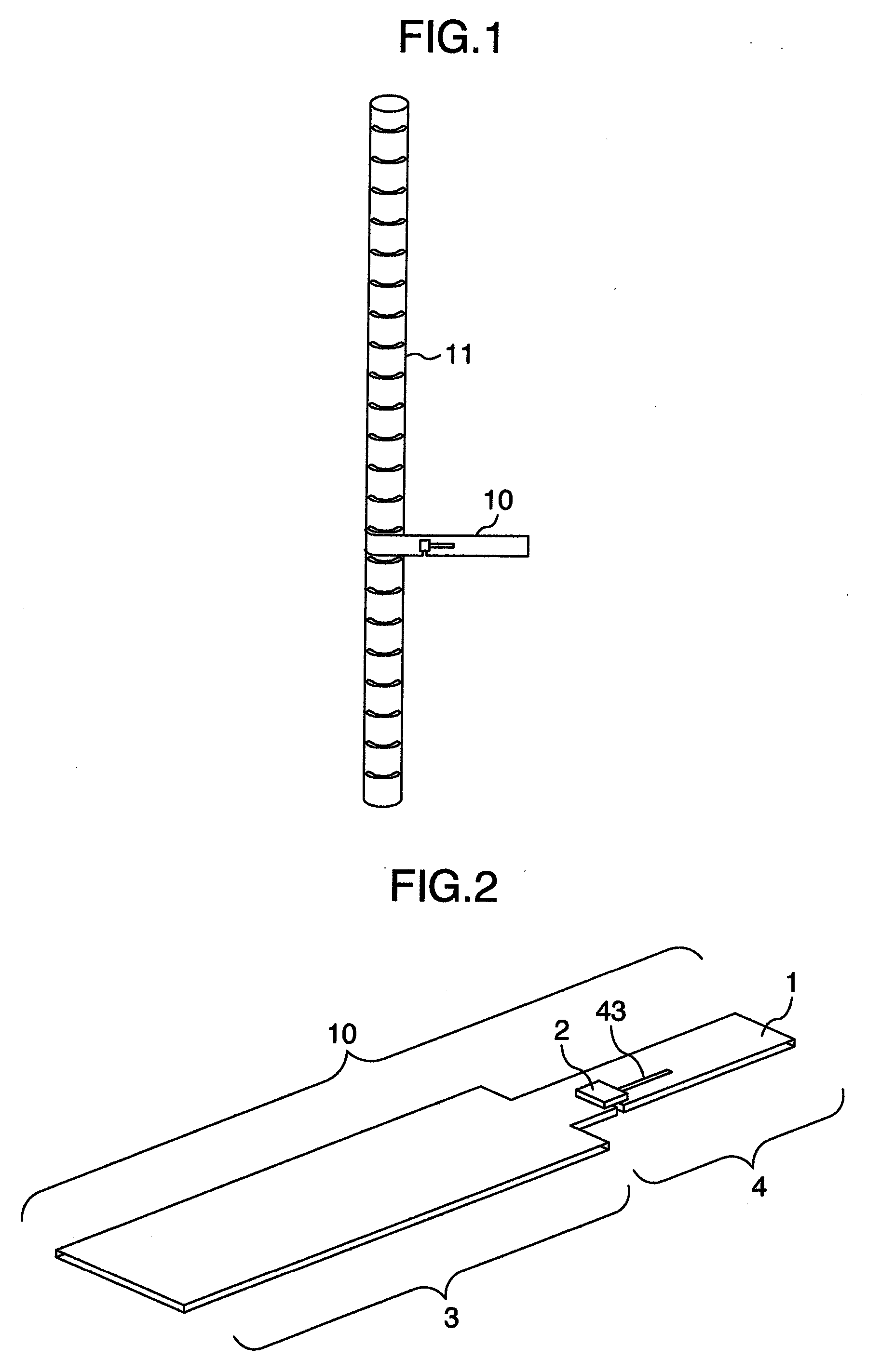
[0030]An RFID tag of the first embodiment will be explained by referring to FIG. 1. An RFID tag 10 mounting an IC chip is put in contact with a reinforcing bar 11 embedded in a concrete structure. The RFID tag 10 and the reinforcing bar 11 may be put in direct contact with each other or connected together through an insulator. The basic principle of this invention is to use the reinforcing bar in the concrete structure as a sub-antenna of the RFID tag.
[0031]Next, by referring to FIG. 2, the construction of the RFID tag 10 of the first embodiment will be explained. The RFID tag 10 comprises a connecting portion 3 and an inlet portion 4. The inlet portion 4 has an antenna 1 made of a conductor, an IC chip 2 of a semiconductor and a slit 43 that forms an impedance matching circuit between the antenna 1 and the IC chip 2. The connection between the antenna 1 and the IC chip 2 will be described later. In this embodiment the bar holding portion 3 and the inlet portion 4 are formed of one ...
second embodiment
[0036]The second embodiment will be explained by referring to FIG. 8, which shows how the RFID tag of this invention is mounted to a connected part of two reinforcing bars 11 crossing at right angles. Two bar holding portions 23 shut in a vertical bar between them and then hold a horizontal bar, thus serving as a binding wire. A mold 12 of the RFID tag serves as a spacer to keep a specified distance between the reinforcing bars and a concrete casting frame.
[0037]As shown in FIG. 9A, a Y-shaped RFID tag 20 has a U-shaped bar holding portion 23 with bar holding portions 25A and 25B spaced apart enough to receive the vertical bar in between. The inlet portion 24 is structured similar to that of the first embodiment. FIG. 9B is a cross section of the RFID tag 20. The RFID tag 20 is molded with epoxy resin that is formed into a cylindrical shape as indicated by 12. When the mold 12 of the RFID tag is used as a spacer, the length of the mold 12 is set equal to a desired spacer length.
[003...
third embodiment
[0039]The third embodiment represents a construction in which an RFID tag is built into a spacer that keeps a specified distance between a concrete casting frame and reinforcing bars, securing a specified thickness of concrete between them. The third embodiment will be explained by referring to FIGS. 11A and 11B. To secure a predetermined thickness of concrete, a circular plastic spacer 13, like the one shown in FIG. 11B, is often used on reinforcing bars 11. The reinforcing bar 11 is held at a central part of the circular spacer 13. In this embodiment a RFID tag 30, such as shown in FIG. 11A, is built into the plastic spacer 13. This construction ensures that the bar holding portion 33 is in contact with the reinforcing bar 11. The bar holding portion 33 forms a center opening surface of the spacer 13. The RFID tag 30 is attached to the spacer 13 with a bonding agent or resin-molded to the spacer. The inlet 34 is similar in construction to the previous embodiment. The use of this a...
PUM
 Abstract
Description
Claims
Application Information