Compact top-loaded, tunable fractal antenna systems for efficient ultrabroadband aircraft operation

a fractal antenna and aircraft technology, applied in the direction of resonant antennas, elongated active elements, radiating element structural forms, etc., can solve the problems of conflicting requirements between ultrabroadband antenna systems and providing antennas for these systems, and the design problem of difficult to solv

Active Publication Date: 2009-11-26
SENSOR SYST
View PDF12 Cites 14 Cited by
  • Summary
  • Abstract
  • Description
  • Claims
  • Application Information

AI Technical Summary

Problems solved by technology

Providing antennas for these systems presents some difficult design problems.
However, these antenna structures must reliably function over long lifetimes in the hostile environment (e.g., vibration and wind pressure) of high-speed aircraft.
Finding ultrabroadband antenna system solutions to these conflicting requirements continues to be a significant challenge.

Method used


Image

  • Compact top-loaded, tunable fractal antenna systems for efficient ultrabroadband aircraft operation
  • Compact top-loaded, tunable fractal antenna systems for efficient ultrabroadband aircraft operation
  • Compact top-loaded, tunable fractal antenna systems for efficient ultrabroadband aircraft operation

Examples


embodiment 20

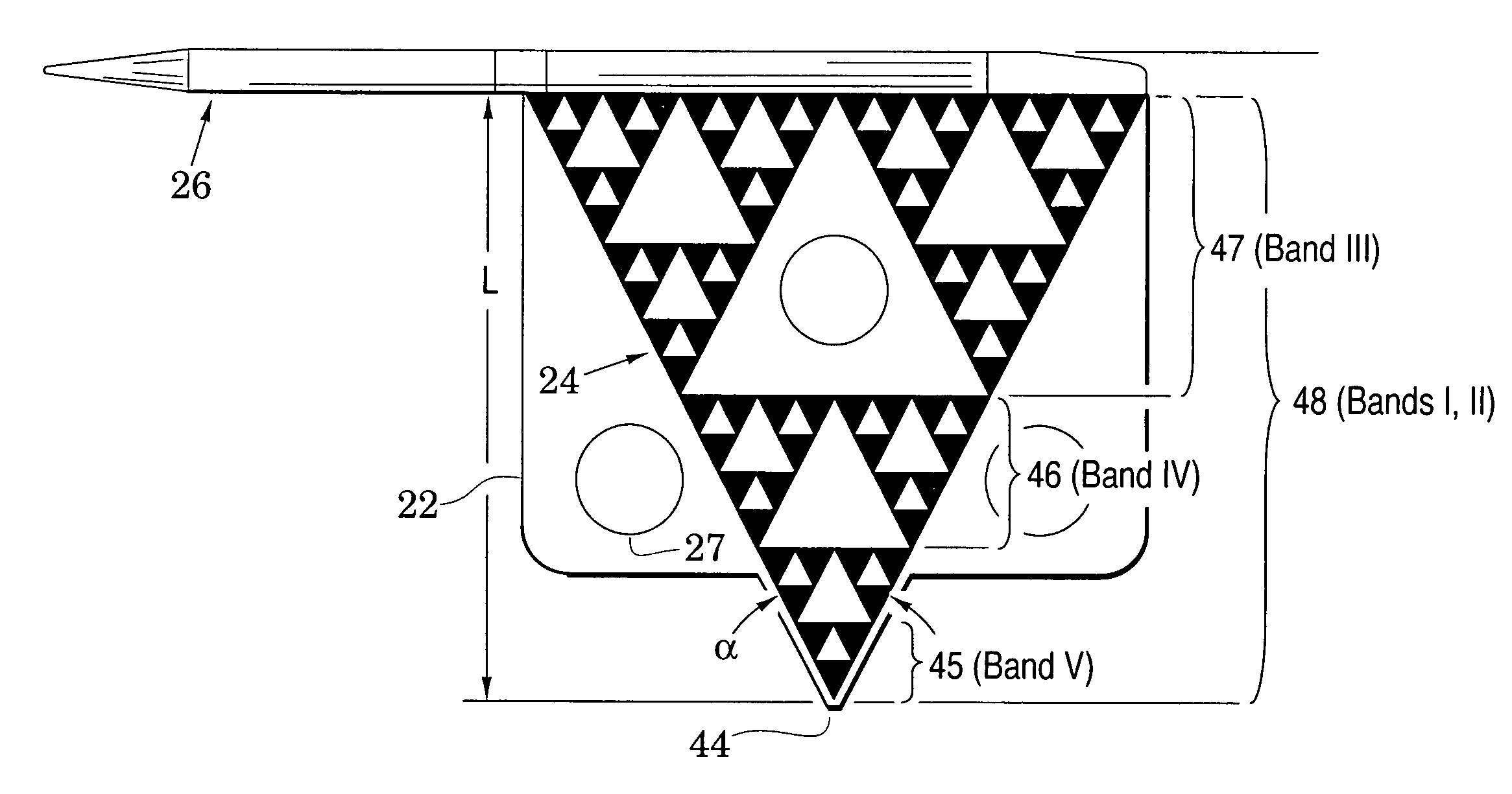
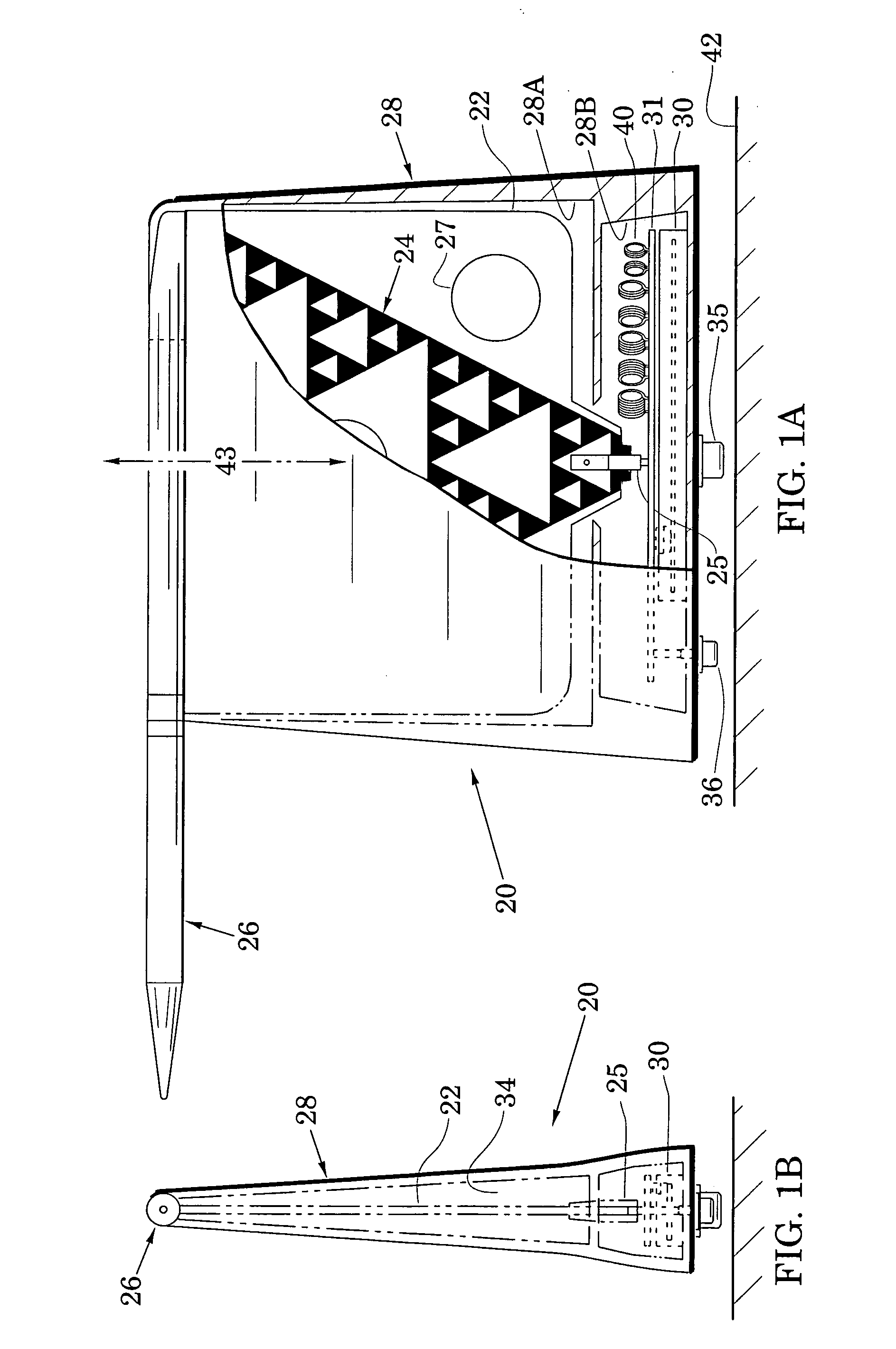
[0024]In particular, FIGS. 1A and 1B illustrate a top-loaded, fractal monopole antenna system embodiment 20 which includes a dielectric substrate 22 that carries a conductive fractal member 24. The fractal member is electrically coupled at a first lower end to a coaxial fitting 25 and at a second upper end to a top load 26. It is noted that a dielectric is a structure in which an electric field can be maintained with a minimum loss of power because the structure (e.g., a polymer sheet) has little ability (or an absence of ability) to conduct electricity. The substrate 22, therefore, has minimal effect on operation of the system 20.

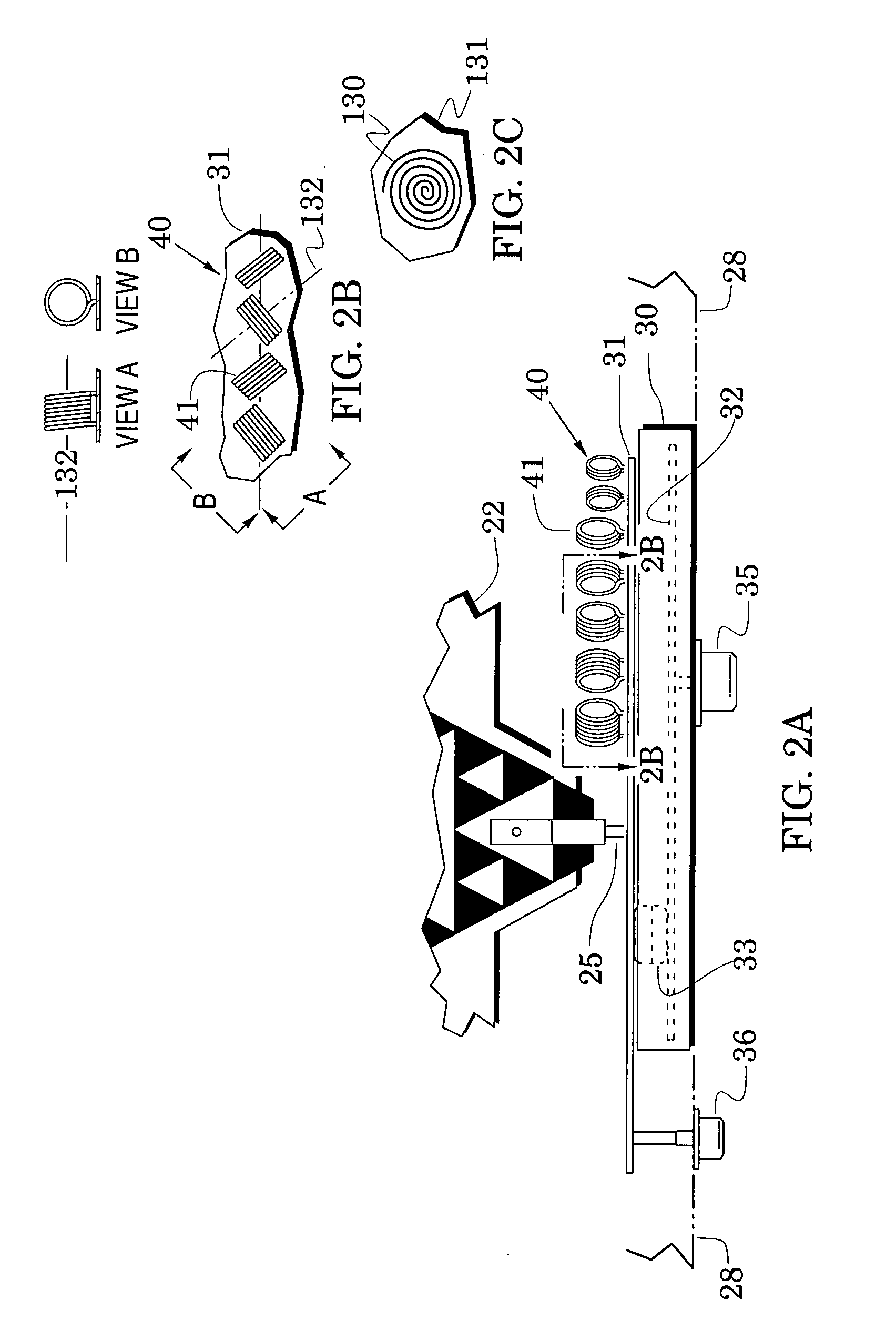
[0025]As illustrated in FIGS. 1A and 1B, the top load 26 is aerodynamically shaped. In addition to its electrical connection to the fractal member 24, the top load may be mechanically coupled to the substrate 22 and is preferably supported by an aerodynamic blade-shaped radome enclosure 28 (formed, for example, of fiberglass). Internally, this protective e...

embodiment 60

[0041]The enhanced radiation efficiency and gain of the system 20 can be advantageously applied to a variety of airborne applications. For example, FIG. 6 shows that a system embodiment 60 can be used to effectively interface with a transceiver 61 via added system structures of a low-band matching circuit 62, the selectable inductor chain 40, and selectable mid and upper band matching circuits 64 that are all coupled between the antenna apex 44 and the transceiver 60 with the aid of a diplexer 65. Selection of the mid and upper band matching circuits and of inductors of the inductor chain 40 is realized with a controller 66 which receives commands 67 from the transceiver and which may be augmented by a memory (e.g., a look-up table 68). The controller 66 may be realized with conventional electronics (e.g., a gate array or an appropriately-programmed microcontroller) and selections of the controller may be facilitated with controlled switching elements such as PIN diodes 69. Processe...

embodiment 80

[0044]This is illustrated with aid of FIG. 8 which illustrates an antenna system embodiment 80 that includes elements of the system 60 of FIG. 6 with like elements indicated by like reference numbers. FIG. 8 shows detailed embodiments of the tuning inductor chain 40, the low band matching circuit 62, and the selectable mid and upper band matching circuits 64 (an arrow 65A in FIG. 8 also shows that the diplexer 65 can be realized with high-pass and low-pass circuits).

[0045]In particular, the matching circuits 64 includes impedance-matching circuits 83, 84, 85 and 86 which may each be selected with diodes 69 that are switched on and off by band bits 81 of commands issued by the controller (66 in FIG. 6). Impedance-matching circuit 83, for example, is switched between the antenna apex 44 and the transceiver 61 to process signals in the frequency band II of FIG. 7A. Impedance-matching circuit 84 is switched between the antenna apex 44 and the transceiver to process signals in frequency ...


PUM


Abstract

Compact top-loaded, fractal monopole antenna system embodiments are provided for multi-band airborne operation over ultrabroadband ranges (e.g., 30 to 2000 MHz). These multi-band embodiments are self-contained, aerodynamic and compact (e.g., blade height less than 9.5 inches) and are power efficient with a low return loss (e.g., less than −7 dB). System embodiments include a set of impedance-matching circuits configured to substantially match an antenna impedance to a predetermined system impedance over a set of predetermined frequency bands. In an embodiment, at least one impedance-matching circuit includes a chain of selectable air-core inductors which are novelly arranged to improve radiation efficiency and prevent damage to support substrates. In an embodiment, a lowest-frequency one of the impedance-matching circuits is configured to process signals having a maximum wavelength λmax wherein a fractal member is configured with a length that does not exceed λmax / 40. System embodiments are configured to respond to a variety of existing radio systems that send commands via different encoding formats.

Description

BACKGROUND OF THE INVENTION[0001]1. Field of the Invention[0002]The present invention relates generally to monopole antennas.[0003]2. Description of the Related Art[0004]Military and commercial airborne communication systems have need for exchange of a variety of communication signals (e.g., voice, data, imagery and video) over an extensive ultrabroadband range of signal frequencies (e.g., 30-2000 MHz). Providing antennas for these systems presents some difficult design problems. In the absence of other restrictions, a designer might consider conventional antenna structures (e.g., dipole and monopole antennas) whose dimensions are a significant portion (e.g., one-fourth) of those of the expected signal wavelengths. However, these antenna structures must reliably function over long lifetimes in the hostile environment (e.g., vibration and wind pressure) of high-speed aircraft. The latter requirement requires compact antennas whose dimensions are far less than otherwise desired and wh...

Claims


Application Information

Patent Timeline
Patent Type & Authority Applications(United States)
IPC IPC(8): H01Q1/50H01Q1/38
CPCH01Q1/36H01Q9/40H01Q9/36
Inventor LIN, ZHEN BIAOLIN, JACK J.Q.ROBIN, SEYMOUR
Owner SENSOR SYST
Why Eureka
Try Eureka