AV System

a technology of av system and av channel, applied in the field of av system, can solve the problems of lag in the timing of image display, complicated video signal processing, and inability to realize the effect of synchronizing the reproduction of conten

Inactive Publication Date: 2009-11-26
YAMAHA CORP
View PDF10 Cites 58 Cited by
  • Summary
  • Abstract
  • Description
  • Claims
  • Application Information

AI Technical Summary

Benefits of technology

[0027]In the AV system of the invention, each AV device transmits and receives information regarding the reproduction timing of content and delays reproduction of content in accordance with an AV device having a latest reproduction timing based on information com

Problems solved by technology

In conventional television devices, the amount of data of video (or image) signals is greater than that of audio (or sound) signals, and the signal processing of video signals is also more complicated than that of audio signals.
This AV system is designed assuming that the amount of data of video signals is greater than that of audio signals and the processing of video signals is also more complicated.
However, in the conventional AV system, the timing of emission of the sound may lag behind the timing of display of the image.
Therefore, if signal processing such as processing for imparting acoustic effects is performed on the audio signal in the AV amplifier, the timing of emission of the sound is delayed by the time required for the s

Method used


Image

  • AV System
  • AV System
  • AV System

Examples


first embodiment

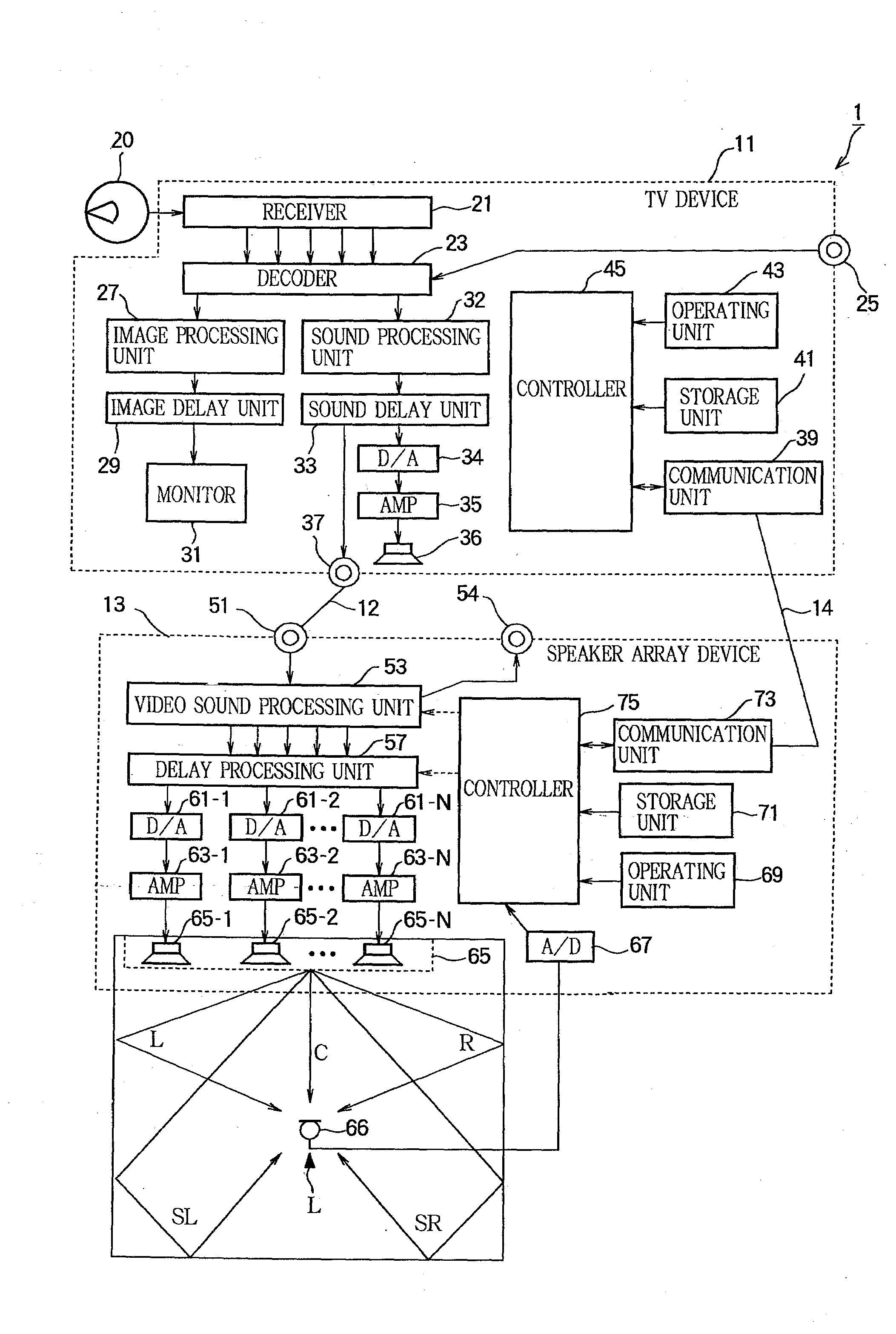
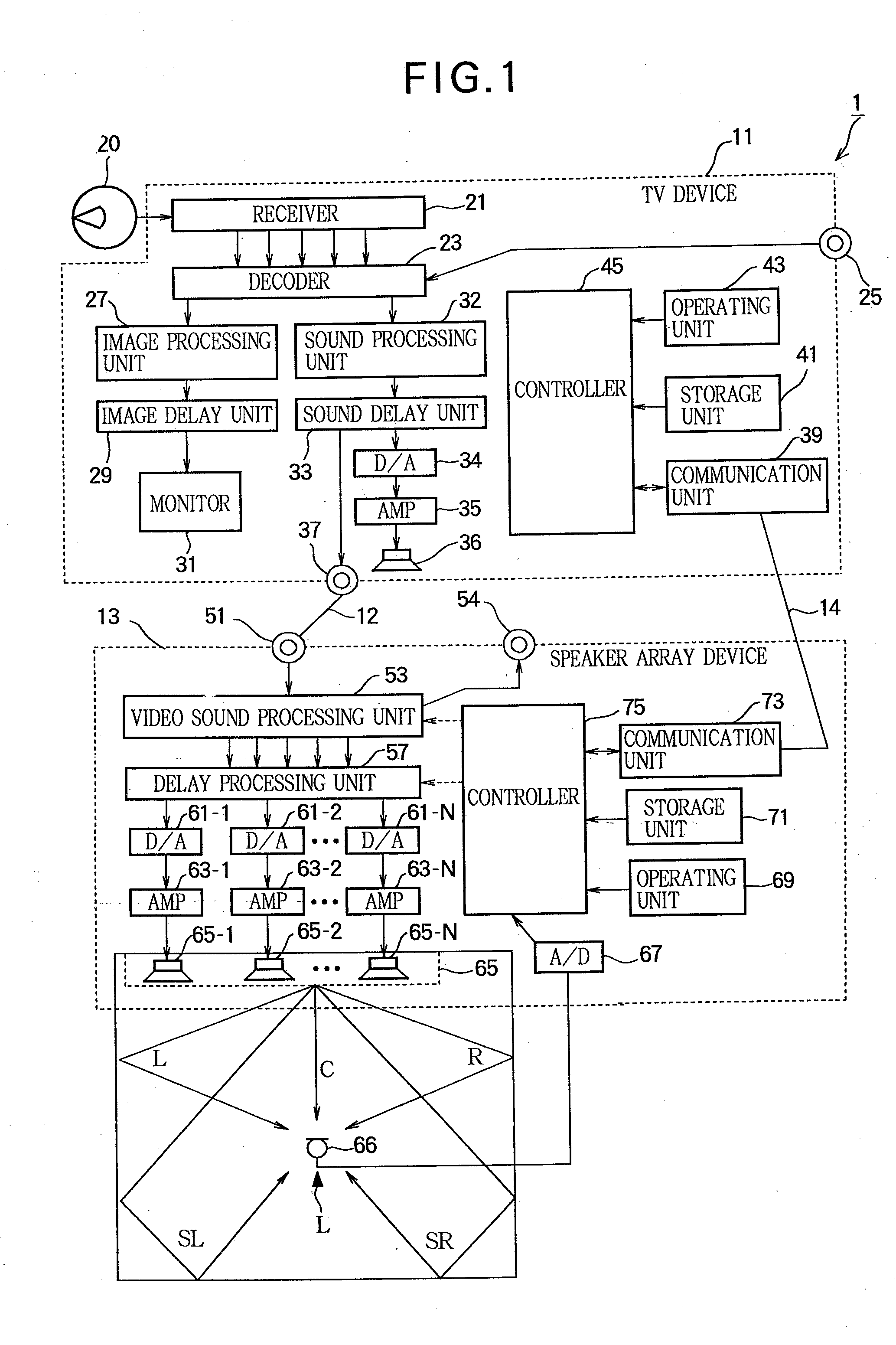
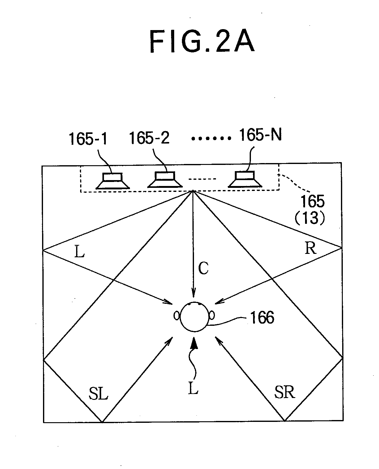
[0041]FIG. 1 is a block diagram illustrating a schematic configuration of an AV system according to a first embodiment of the invention. FIG. 2 illustrates the state and the processing and propagation times of each sound beam output by a speaker array device.

[0042]The AV system 1 according to the first embodiment is a 5ch surround system that includes two AV devices, i.e., a speaker array device 13 having both AV amplifier and speaker functions and a television device 11. In the AV system 1, the television device 11 receives a broadcast and a monitor 31 of the television device 11 displays an image of the broadcast and the speaker array device 13 emits a sound of the broadcast.

[0043]In the following description, a front left channel in the 5ch surround system is referred to as “Left (L) ch”, a front right channel is referred to as “Right (R) ch”, a center channel is referred to as “Center (C) ch”, a rear left channel is referred to as “Surround Left (SL) ch”, and a rear right channe...

second embodiment

[0109]A description will now be given of an AV system 2 associated with a second embodiment of the invention. FIG. 5 is a block diagram illustrating a schematic configuration of the AV system associated with the second embodiment of the invention.

[0110]The AV system 2 includes a television device 11, a speaker array device 13, and a DVD player (source device) 15.

[0111]A detailed description of the television device 11 and the speaker array device 13 is omitted since they have the same configurations as those of FIG. 1. The AV system 2 associated with the second embodiment is different from that of the first embodiment in that content is transmitted from the DVD player 15 to the television device 11 and the speaker array device 13.

[0112]The DVD player 15 includes a DVD reproduction unit 81, a decoder 83, a video signal output unit 85, an audio signal output unit 87, a communication unit 89, a controller 91, a storage unit 93, and an operating unit 95.

[0113]The DVD reproduction unit 8...

third embodiment

[0126]FIG. 6 is a block diagram illustrating a schematic configuration of an AV system associated with a third embodiment of the invention. FIG. 7 is a timing chart of image processing and sound processing in the AV system. The AV system 3 associated with the third embodiment of the invention is different from those of the first and second embodiments in that content is transmitted from a DVD player 15′ to a television device 11 through a speaker array device 13′.

[0127]In the AV system 3 shown in FIG. 3, the television device 11 has the same configuration as shown in FIGS. 1 and 5. The speaker array device 13′ is only partially different from the speaker array device 13 shown in FIG. 5. The DVD player 15′ is also only partially different from the DVD player 15 shown in FIG. 5. Thus, the following description will be given of only the different features of the elements of each device.

[0128]The speaker array device 13′ is configured by replacing the signal input unit 51 in the speaker...


PUM


Abstract

AV content is input and output in an AV system. In the AV system, a plurality of AV devices process a signal of the content to reproduce the content. A source device broadcasts the content to each of the AV devices. In each of the AV devices, a reproduction unit receives the content broadcast by the source device and performs reproduction processing on the received content. A communication unit communicates reproduction processing time information with another AV device, the reproduction processing time information indicating a time required for the reproduction processing of the content. A delay unit delays a time to reproduce the content, such that the delay unit delays reproduction of the content in accordance with an AV device having a latest reproduction timing based on the reproduction processing time information.

Description

BACKGROUND OF THE INVENTION[0001]1. Technical Field of the Invention[0002]The present invention relates to an AV system which reproduces content through a plurality of AV devices.[0003]2. Description of the Related Art[0004]In conventional television devices, the amount of data of video (or image) signals is greater than that of audio (or sound) signals, and the signal processing of video signals is also more complicated than that of audio signals. Therefore, if a sound and an image are directly output immediately after they are processed, the sound is first output so that the sound and the image are not synchronized. Thus, in conventional television devices, the timing of emission of a sound through an internal speaker or an internal audio output terminal is delayed so that the sound is synchronized (i.e., lip-synced) with movement of lips (i.e., an image displayed on the monitor).[0005]In a conventional AV system, when a DVD player reproduces content, a television receiver process...

Claims


Application Information

Patent Timeline
IPC IPC(8): H04N9/475H04N7/173H04N5/60H04N21/436H04N21/44H04S7/00
CPCH04S3/00H04N5/04H04N21/8106H04R2203/12H04N21/439H04N21/4307H04N21/43072
Inventor MATSUMOTO, KEISHIMURATA, MORIHIRO
Owner YAMAHA CORP
Why Eureka
Try Eureka