Reflection reducing film, optical member and optical system

a technology of reducing film and reducing film, which is applied in the field of reflection reducing film, optical member and optical system, can solve the problems of insufficient anti-reflection performance of anti-reflection film described in the above patent document 1, insufficient anti-reflection performance in the near-infrared region, and no anti-reflection film exhibiting excellent low reflectance characteristics in the entire visible light region, etc., to achieve excellent chromaticity balance and excellent chromaticity balance balan

Inactive Publication Date: 2009-11-26
FUJIFILM CORP
View PDF1 Cites 24 Cited by
  • Summary
  • Abstract
  • Description
  • Claims
  • Application Information

AI Technical Summary

Benefits of technology

[0025]According to a reflection reducing film and an optical member of the invention, first to eighth layers of the reflection reducing layer on a substrate are made of materials having predetermined refractive indices and thus a reflectance for normal incident light and oblique incident light can be sufficiently reduced in a wide wavelength band from a visible region to a near-infrared region. Accordingly, when the reflection reducing film and the optical member of the invention are applied to an optical system of an image pickup apparatus such as a broadcasting camera, the occurrence of flare and ghost can be suppressed and a more excellent chromaticity balance can be obtained. Moreover, as being able to cope with both of the visible region and

Problems solved by technology

Herein, when the number of the optical members increases, a total amount of the reflection light increases and thus defects, for example, flare and ghost occur in images of a broadcasting camera.
However, the antireflection film described in the above Patent Document 1 has insufficient antireflection performance in a near-infrared region.
However, the number of antireflection films also exhibiting sufficiently low

Method used


Image

  • Reflection reducing film, optical member and optical system
  • Reflection reducing film, optical member and optical system
  • Reflection reducing film, optical member and optical system

Examples


first embodiment

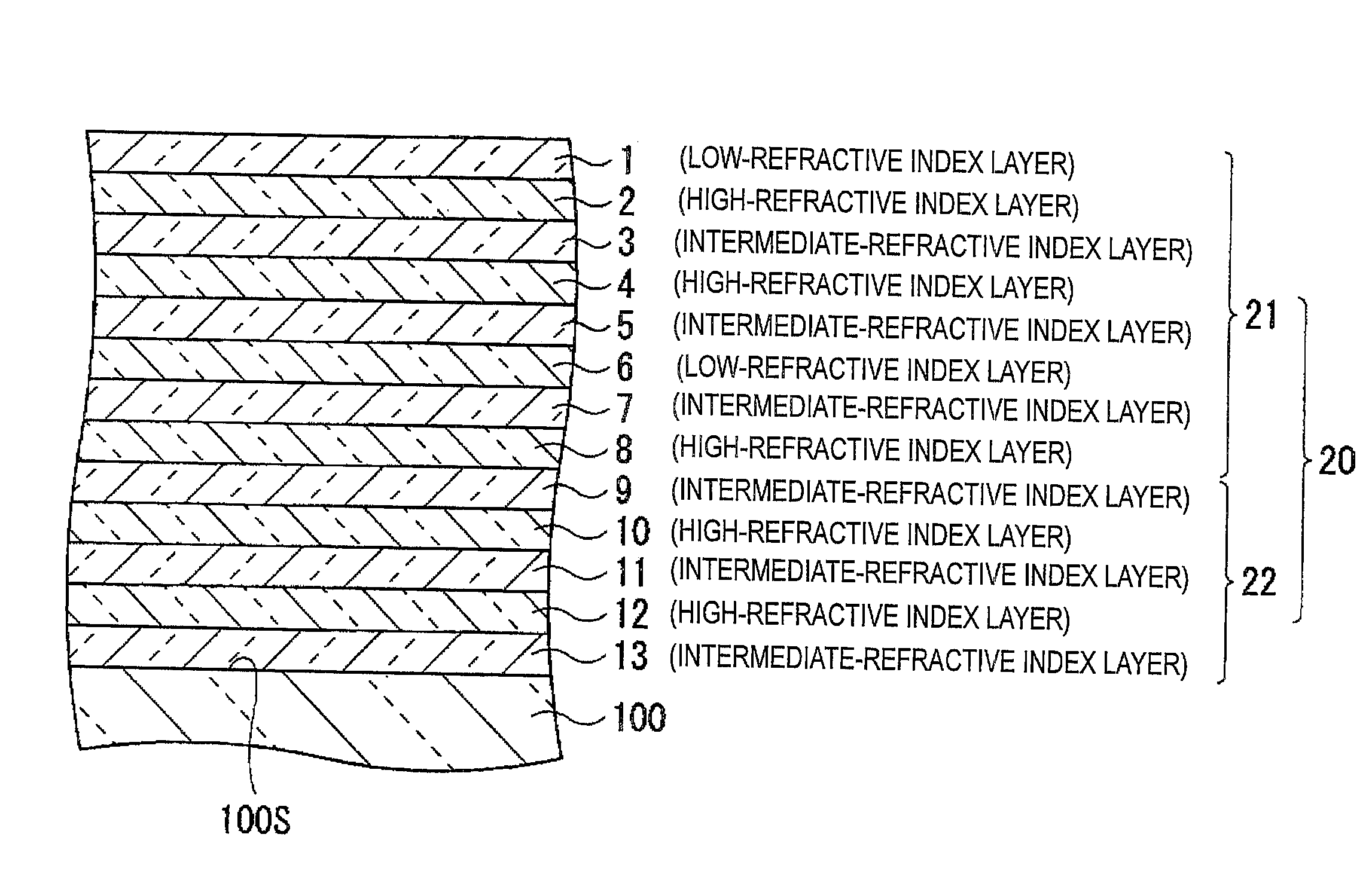
[0073]FIG. 1 is a schematic cross-sectional view showing the configuration of a reflection reducing film 20 according to a first embodiment of the invention. The reflection reducing film 20 of FIG. 1 corresponds to first numerical examples (Tables 3 to 9 and FIGS. 14A to 20B) to be described later.

[0074]The reflection reducing film 20 is a multilayer film composed of total 13 layers provided on a surface 100S of an optical substrate 100 and first to thirteenth layers 1 to 13 are sequentially laminated from the opposite side to the optical substrate 100. The first to eighth layers 1 to 8 serve as a reflection reducing layer 21 and the ninth to thirteenth layers 9 to 13 serve as a buffer layer 22. The buffer layer 22 is provided to come into close contact with both of the surface 100S of the optical substrate 100 and the eights layer 8 of the reflection reducing layer 21, and has a multilayer structure. The buffer layer 22 functions to moderate a sudden change in refractive index betw...

second embodiment

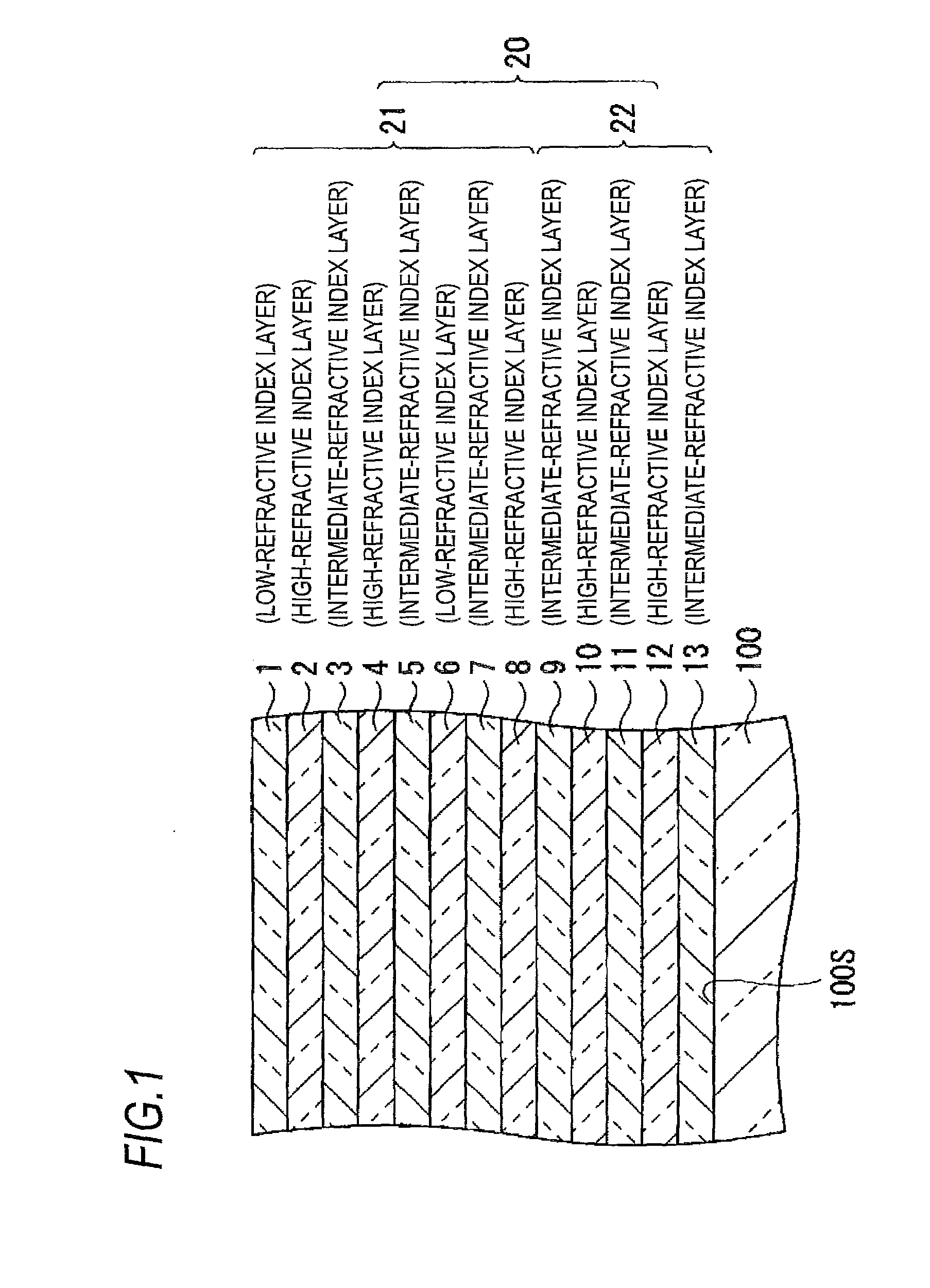
[0082]FIG. 2 is a schematic cross-sectional view showing the configuration of a reflection reducing film 30 according to a second embodiment of the invention. The reflection reducing film 30 of FIG. 2 corresponds to second numerical examples (Tables 10 to 12 and FIGS. 21A to 23B) to be described later.

[0083]The reflection reducing film 30 is a multilayer film composed of total 11 layers provided on a surface 100S of an optical substrate 100 and first to eleventh layers 1 to 11 are sequentially laminated from the opposite side to the optical substrate 100. Among them, the first to eighth layers 1 to 8 serve as a reflection reducing layer 31 and the ninth to eleventh layers 9 to 11 serve as a buffer layer 32. The reflection reducing layer 31 has the same configuration as the reflection reducing layer 21. In the following explanation for the reflection reducing film 30, constituent elements which are substantially different from in the reflection reducing film 20 according to the first...

third embodiment

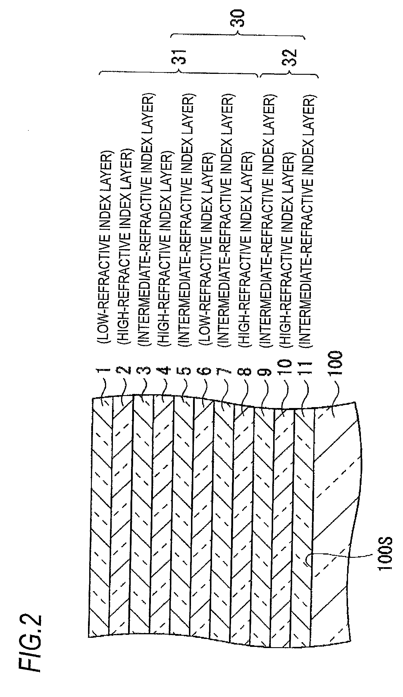
[0087]FIG. 3 is a schematic cross-sectional view showing the configuration of a reflection reducing film 40 according to a third embodiment of the invention. The reflection reducing film 40 of FIG. 3 corresponds to third numerical examples (Tables 13 to 16 and FIGS. 24A to 27B) to be described later.

[0088]The reflection reducing film 40 is a multilayer film composed of total 12 layers provided on a surface 100S of an optical substrate 100 and first to twelfth layers 1 to 12 are sequentially laminated from the opposite side to the optical substrate 100. Among them, the first to eighth layers 1 to 8 serve as a reflection reducing layer 41 and the ninth to twelfth layers 9 to 12 serve as a buffer layer 42. The reflection reducing layer 41 has the same configuration as the reflection reducing layer 21. In the following explanation for the reflection reducing film 40, constituent elements which are substantially different from in the reflection reducing film 40 according to the first emb...


PUM

PropertyMeasurementUnit
Fractionaaaaaaaaaa
Fractionaaaaaaaaaa
Fractionaaaaaaaaaa

Abstract

A reflection reducing film is provided on a surface of an optical substrate, and is sequentially provided with a buffer layer and a reflection reducing layer. The reflection reducing layer includes first to eighth layers sequentially laminated from the side of the buffer layer. The first and sixth layers are made of a low-refractive index material having a refractive index in the range of 1.35 to 1.50 at the d-line, the third, fifth and seventh layers are made of an intermediate-refractive index material having a refractive index in the range of 1.55 to 1.85 at the d-line, and the second, fourth and eighth layers are made of a high-refractive index material having a refractive index in the range of 1.70 to 2.50 at the d-line.

Description

CROSS-REFERENCE TO RELATED APPLICATIONS[0001]This application is based on and claims priority under 35 USC 119 from Japanese Patent Application No. 2008-134224 filed May 22, 2008 and Japanese Patent Application No. 2008-134225 filed May 22, 2008; the entire contents of which are incorporated herein by reference.BACKGROUND[0002]1. Technical Field[0003]The present invention relates to a reflection reducing film which is formed on one face of an optical member such as a lens, a filter and the like to exhibit a reflection reducing effect with respect to light having a predetermined wavelength band, and an optical member and an optical system which have the reflection reducing film.[0004]2. Related Art[0005]Generally, an image pickup apparatus such as a photographic camera or a TV broadcasting camera has a number of optical members such as lenses, prisms, filters and the like disposed on an optical path thereof. When light is incident on surfaces of the respective optical members, a port...

Claims


Application Information

Patent Timeline
IPC IPC(8): G02B1/11
CPCY10T428/24942G02B1/115
Inventor TERAYAMA, ETSUO
Owner FUJIFILM CORP
Why Eureka
Try Eureka