
Calculation of a destination time alignment value to be used by a user equipment in a destination cell after a handover

Active Publication Date: 2009-11-26
TELEFON AB LM ERICSSON (PUBL)
View PDF6 Cites 7 Cited by
  • Summary
  • Abstract
  • Description
  • Claims
  • Application Information

AI Technical Summary

Benefits of technology

[0008]It is therefore an object of the present invention to provide a mechanism for timing of mobile transmission at handover that will work for any cell configuration both co-located and non-co-located cases.
[0012]An advantage with the present invention is that usage of shortened bursts can be avoided at handover which implies that the handover interruption will be minimized.
[0014]A further advantage with the present invention is that means to synchronize base stations with each other also are possible to provide.

Problems solved by technology

Shortened bursts are short enough to allow for enough time margins for the largest cells and may or may not contain user data payload.
The problem with this solution is that it is limited to the case where the serving cell and target cells are co-located, i.e. using the same base station and / or the same antenna.

Method used


Image

  • Calculation of a destination time alignment value to be used by a user equipment in a destination cell after a handover
  • Calculation of a destination time alignment value to be used by a user equipment in a destination cell after a handover
  • Calculation of a destination time alignment value to be used by a user equipment in a destination cell after a handover

Examples


Embodiment Construction

[0019]The invention is defined as a method and an arrangement which may be put into practice in the embodiments described below.

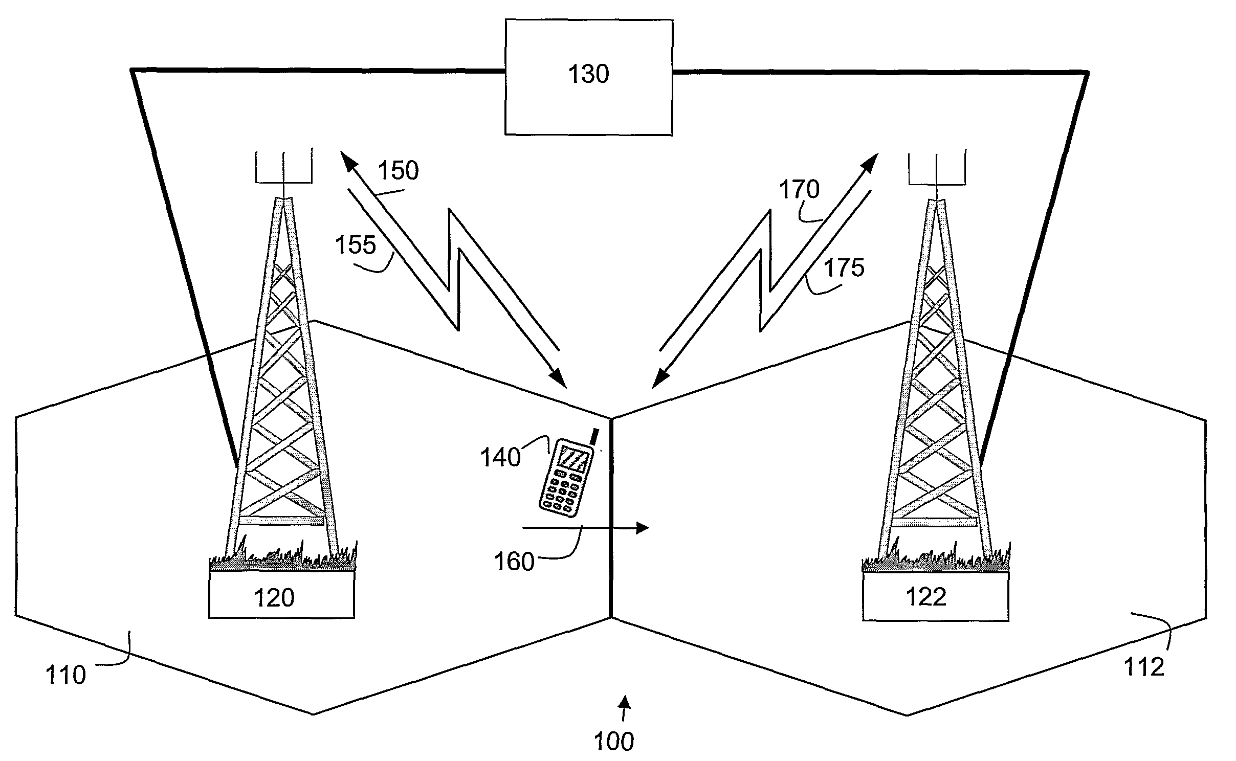
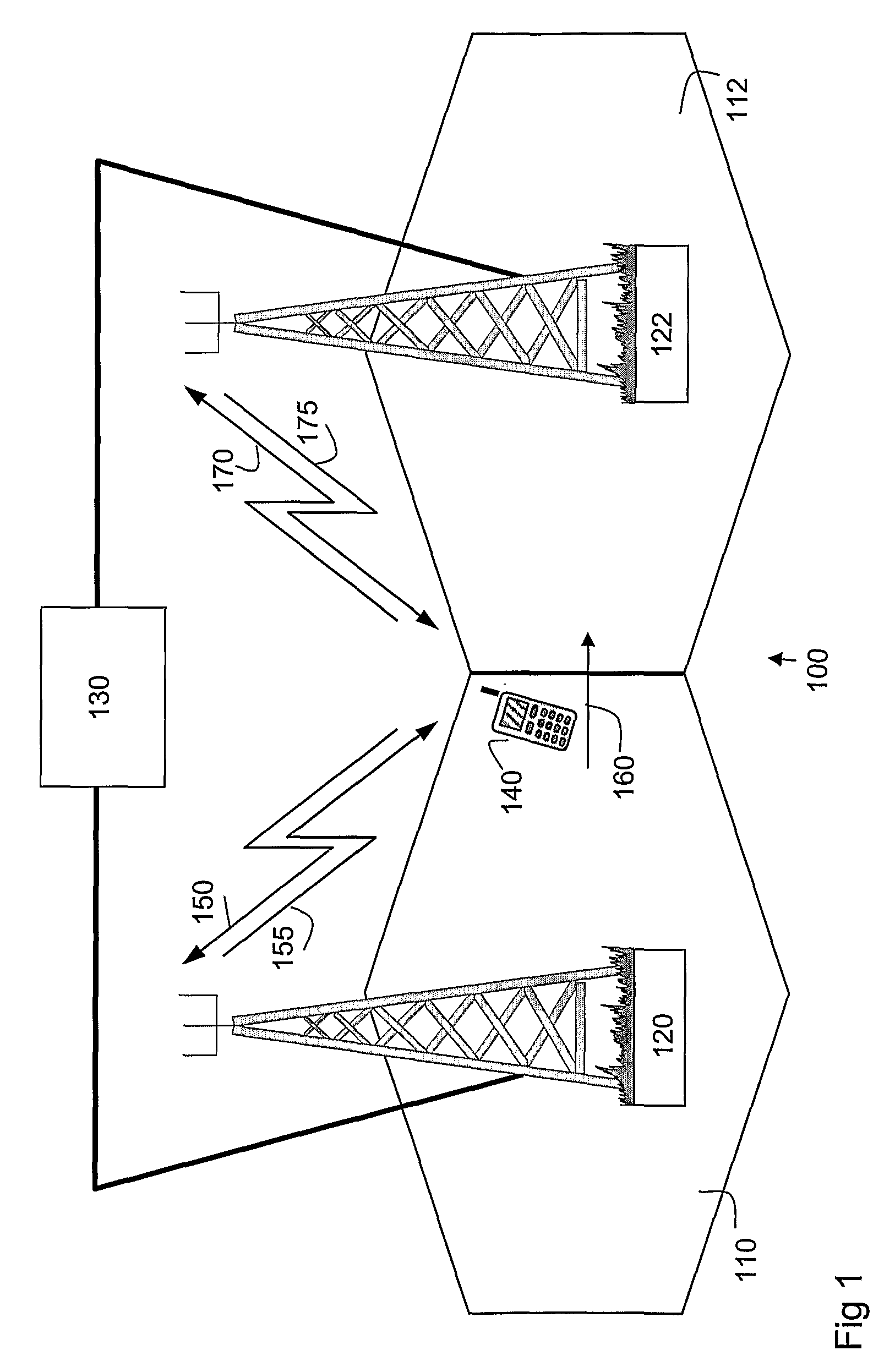
[0020]FIG. 1 depicts a radio access network 100 using technologies such as e.g. Wideband Code Division Multiple Access (WCDMA), Time Division Duplex (TDD) mode Radio Access Network Long Term Evolution (RAN LTE), Global System for Mobile communication (GSM), Personal Digital Cellular (PDC), Worldwide Interoperability for Microwave Access (WIMAX) or any TDD or TDMA system. The radio access network 100 comprises a number of cells, whereof two cells, cell 110 and cell 112 are depicted in FIG. 1. Each of the cells is served by a radio base station such that cell 110 is served by radio base station 120 and cell 112 is served by radio base station 122. The cells 110, 112 and radio base stations 120, 122 are controlled by a network node 130, which network node 130 may be one or more network nodes that performs different controlling functionality, the network node m...


PUM


Abstract

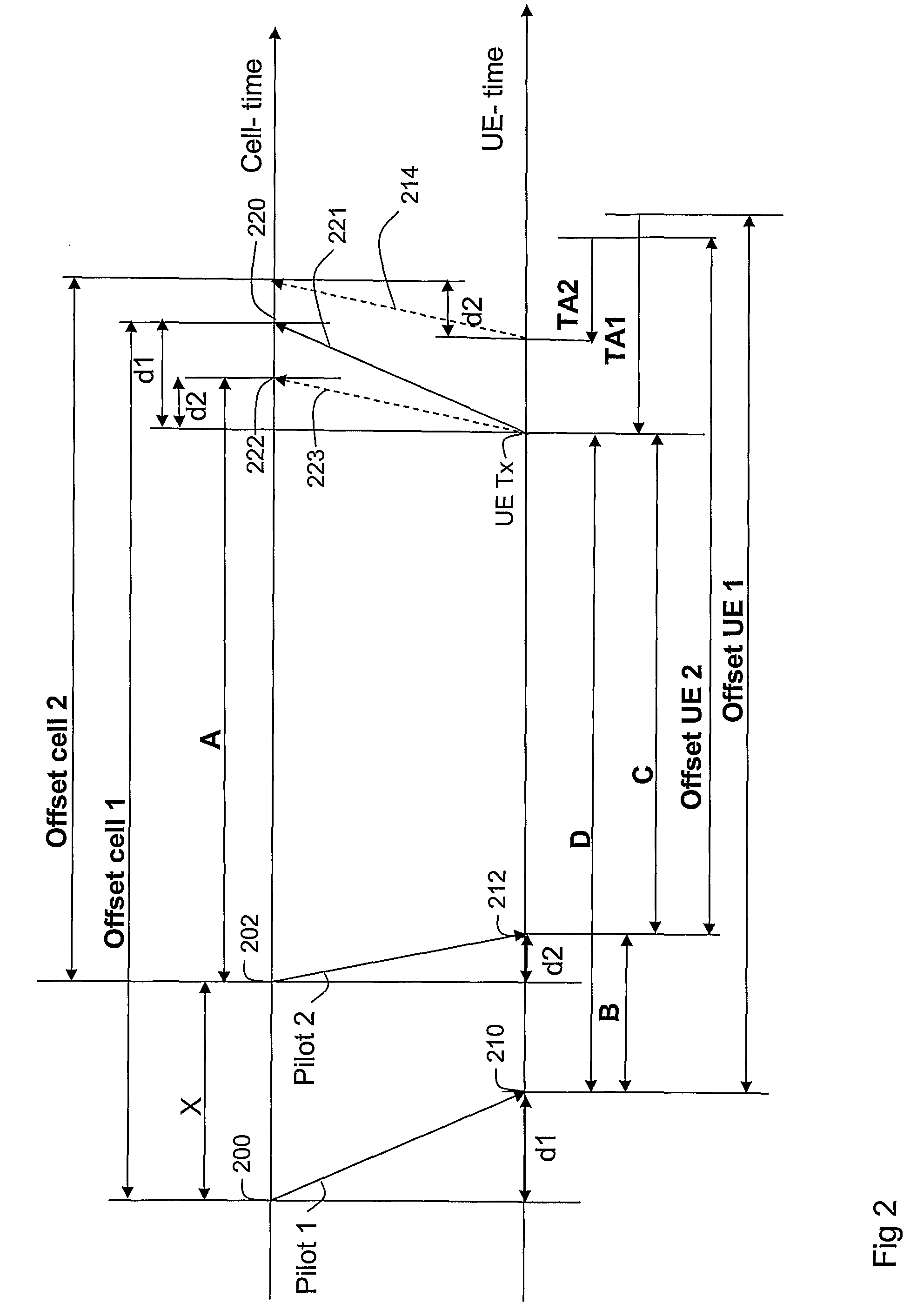
The invention relates to a method and arrangement for managing a calculation of a destination time alignment value TA2 to be used by a user equipment in a destination cell after a handover in a radio access network. The radio access network comprises a source cell, the destination cell and a user equipment which is adapted to switch to communicate with a destination base station comprised in the destination cell after the handover. The source cell is adapted to transmit a first reference signal and the destination cell is adapted to transmit a second reference signal. The method comprises the step of obtaining a first information comprising the time difference A between a point of time when the second reference signal is transmitted and a point of time when the destination cell receives the user equipment transmission, obtaining a second information comprising the time difference C between the point of time when second reference signal is received and a point of time when the user equipment transmission is transmitted, and calculating the destination time alignment TA2, by means of the formula [TA2=C−A].

Description

TECHNICAL FIELD[0001]The present invention relates to a method and an arrangement in a radio access network. In particular the present invention relates to managing calculation of a destination time alignment value to be used by a user equipment in a destination cell after a handover.BACKGROUND OF THE INVENTION[0002]Access schemes where user equipment transmissions need to be time aligned at the base station receiver require timing adjustments of the user equipment transmission to compensate for varying propagation delay between user equipments. This to avoid having to use unnecessary large time guard between users when having different and varying propagation delay between user equipments and base station. Basically all Time Division Multiple Access (TDMA) based access schemes such as Global System for Mobile communication (GSM), Personal Digital Cellular (PDC) and Time Division Multiple Access (TDMA) use some sort of time alignment control.[0003]Time alignment adjustments of user ...

Claims


Application Information

Patent Timeline
IPC IPC(8): H04W36/00
CPCH04B7/2678H04W56/004H04W36/0072
Inventor MULLER, WALTER
Owner TELEFON AB LM ERICSSON (PUBL)
Learn More