Solid oxide reversible fuel cell with improved electrode composition
a solid oxide and electrode composition technology, applied in the field of reversible solid oxide fuel and electrolyzer cells, can solve the problems of increasing the cost of fuel cells, and prone to delamination of sorfc oxidant electrodes
- Summary
- Abstract
- Description
- Claims
- Application Information
AI Technical Summary
Benefits of technology
Problems solved by technology
Method used
Image
Examples
first embodiment
[0008]In the invention, the inventors realized that electrode delamination in a solid oxide electrolyzer cell or solid oxide reversible fuel cell may be reduced if an interfacial layer is provided between the electrolyte and the electrode. Preferably, the interfacial layer comprises a gadolinia doped ceria (“GDC”) layer. The interfacial layer prevents or reduces delamination of the electrode from the electrolyte. Thus, the interfacial layer may be considered a part of the electrolyte or an intervening layer located between the electrolyte and the electrode.
[0009]The interfacial layer may be located between the fuel electrode and the electrolyte to prevent or reduce fuel electrode delamination. Alternatively, the interfacial layer may be located between the oxidant electrode and the electrolyte to prevent or reduce oxidant electrode delamination. Preferably a first interfacial layer is located between the fuel electrode and the electrolyte and a second interfacial layer is located be...
second embodiment
[0010]In the invention, the inventors realized that anodic degradation of the fuel electrode of the above mentioned cell may be reduced if the fuel electrode comprises a cermet comprising nickel and one or both of a doped zirconia and gadolinia doped ceria. The use of a nickel with gadolinia doped ceria and / or a doped zirconia avoids the use of expensive noble metals in the electrodes thus reducing the cost of the device. However, if desired, other materials, including noble metals, may be added to the fuel electrode.
third embodiment
[0011]In the invention, the oxidant electrode of the above mentioned cell comprises LSM and one or both of GDC and a doped zirconia. For example, the oxidant electrode comprises an active layer comprising LSM and scandia stabilized zirconia (“SSZ”) or LSM, yttria stabilized zirconia (“YSZ”) and GDC, and a current collector layer comprising LSM or another conductive perovskite material, such as LSCo. The active layer is preferably located between the electrolyte and the current collector layer.
[0012]The features of the first, second and third embodiments of the invention may be used in any combination. For example, the fuel and / or oxidant electrode materials and the interfacial layer(s) described above may be used in any suitable combination either together or separately.
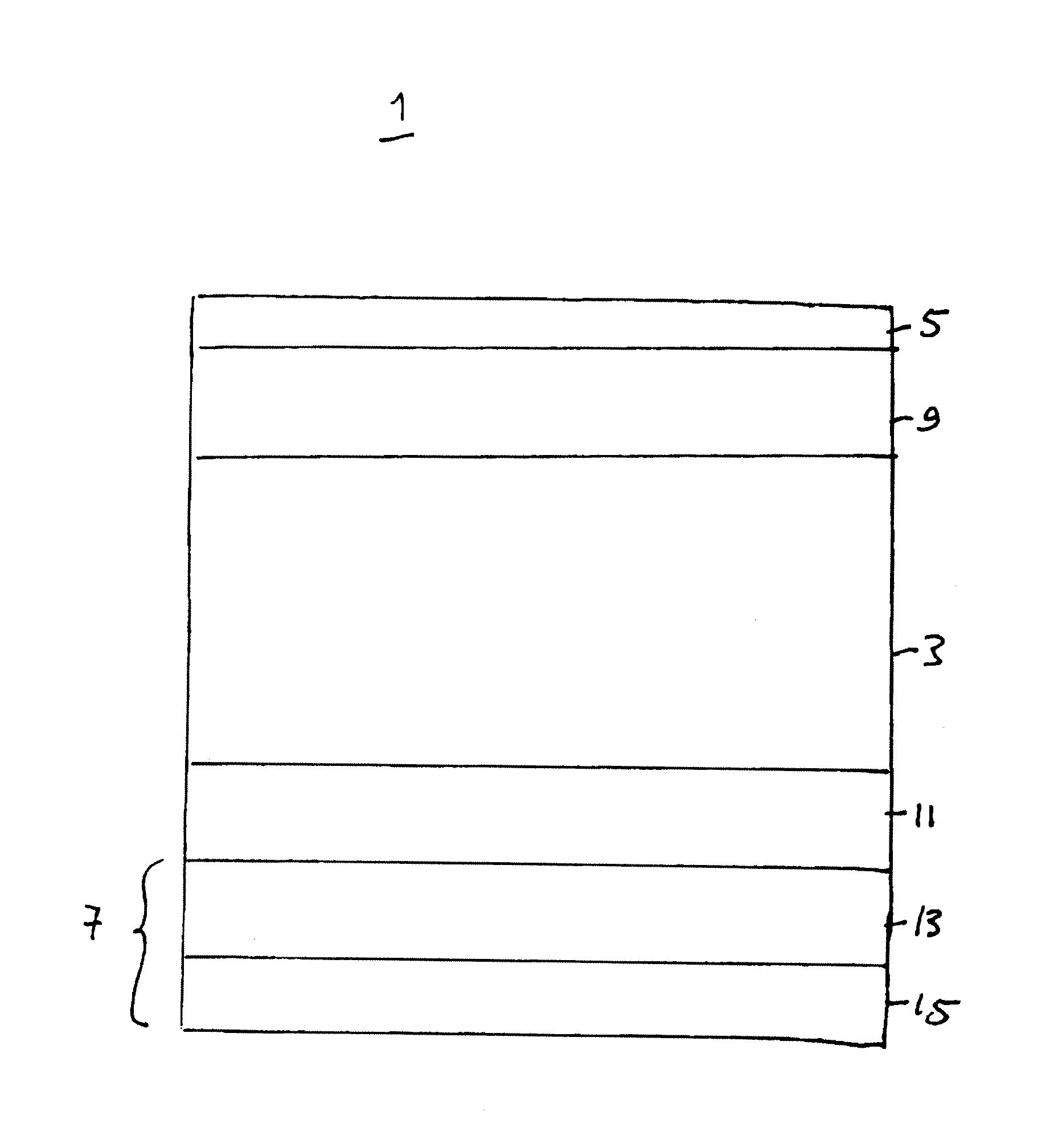
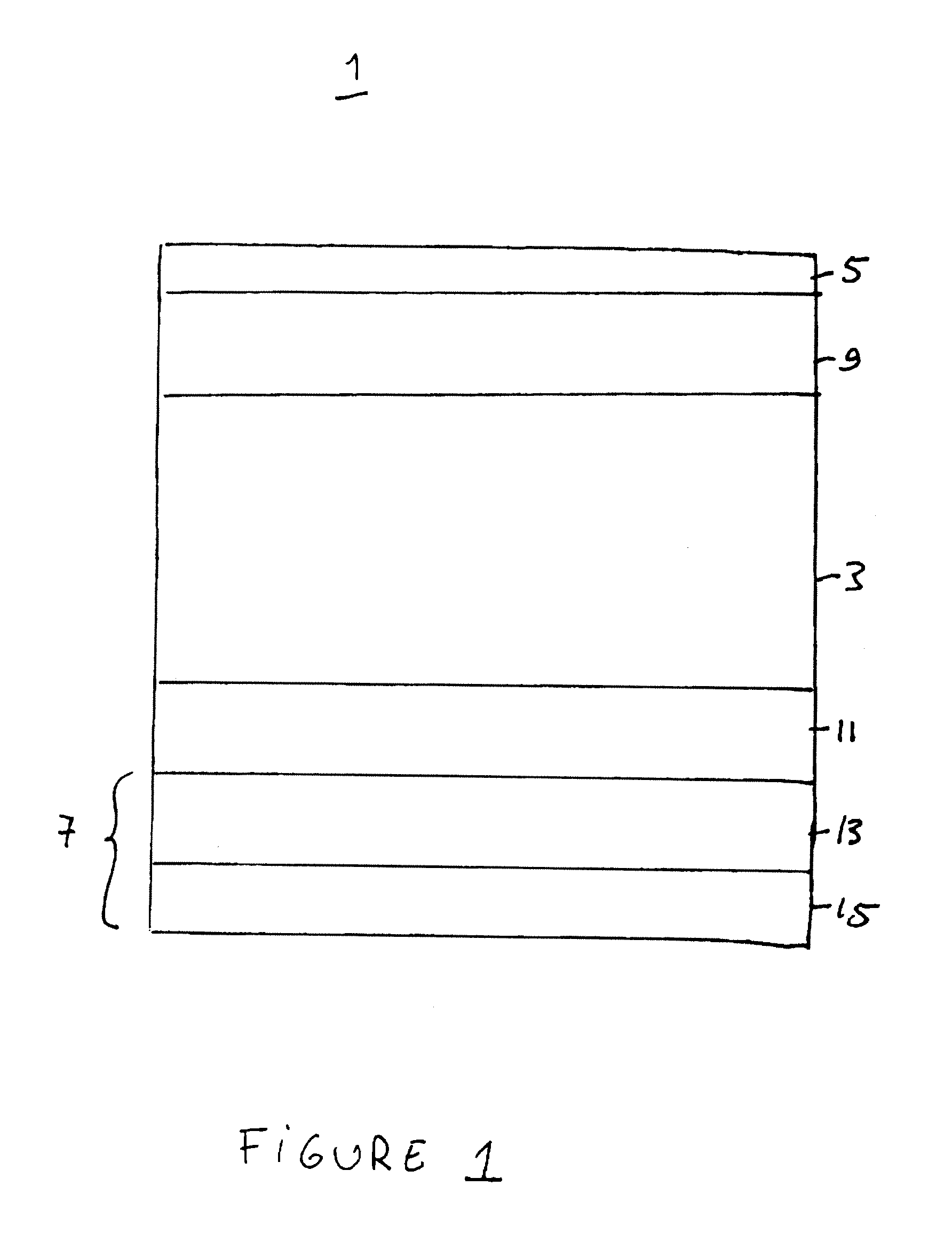
[0013]FIG. 1 shows an exemplary solid oxide electrolyzer cell according to the first through third embodiments of the present invention. This cell is preferably operated reversibly (i.e., it comprises a solid oxide r...
PUM
| Property | Measurement | Unit |
|---|---|---|
| electrical energy | aaaaa | aaaaa |
| conductive | aaaaa | aaaaa |
| composition | aaaaa | aaaaa |
Abstract
Description
Claims
Application Information
 - R&D
- Intellectual Property
- Life Sciences
- Materials
- Tech Scout
- Unparalleled Data Quality
- Higher Quality Content
- 60% Fewer Hallucinations
Browse by: Latest US Patents, China's latest patents, Technical Efficacy Thesaurus, Application Domain, Technology Topic, Popular Technical Reports.
© 2025 PatSnap. All rights reserved.Legal|Privacy policy|Modern Slavery Act Transparency Statement|Sitemap|About US| Contact US: help@patsnap.com


