Laser sealing of injector solenoids

a solenoid coil and solenoid technology, applied in the direction of connection contact material, magnets, magnets, etc., can solve the problems of premature coil failure, difficult chemical bonding of the overmold plastic to the plastic of the bobbin, and difficult to provide a reliable hermetic seal between the wire-wound bobbin and the overmold, so as to improve the durability and performance of the solenoid coil/connector assembly, and improve the reliability of such a fuel

Inactive Publication Date: 2009-11-26
DELPHI TECH INC
View PDF12 Cites 9 Cited by
  • Summary
  • Abstract
  • Description
  • Claims
  • Application Information

AI Technical Summary

Benefits of technology

[0011]The near infrared laser light is used in accordance with the invention to locally heat the material of the bobbin and to effectively melt both materials at the interface between the bobbin and the overmold. On removal of the laser, the molten materials resolidify and a hermetic seam between the bobbin and the overmold is formed. By using the laser welding process to hermetically seal the interfaces between the top flange and the bottom flange of the bobbin and the overmold, the coil wires become hermetically sealed to external fluids, improving the durability and performance of the solenoid coil / connector assembly. By including such a solenoid coil / connector assembly in a fuel injector assembly of an internal combustion engine, the reliability of such a fuel injector may be improved and the working life may be prolonged. Furthermore, by using the laser welding process to hermetically seal the interfaces between the top flange and the bottom flange of the bobbin and the overmold, added parts, such as o-rings, or added sealants can be eliminated.

Problems solved by technology

In the prior art, it has proved difficult to provide a reliable hermetic seal between the wire-wound bobbin and the overmold.
One of the issues with overmolding the wire-wound bobbin is that it is difficult to chemically bond the plastic of the overmold to the plastic of the bobbin even if similar materials are chosen.
The lack of a hermetic seal may allow fluids under pressure to migrate into the coil area and may lead to premature coil failure depending on the amount and type of fluid intrusion.
Such seals offer some improvement in performance but include additional parts, are more expensive to install or manufacture, and are vulnerable to damage during assembly of a solenoid, thus negating their advantage.
Further, damage to an o-ring or seal may not be readily identified at the time the damage occurs and may become evident only upon failure of the solenoid in customer usage.

Method used


Image

  • Laser sealing of injector solenoids
  • Laser sealing of injector solenoids
  • Laser sealing of injector solenoids

Examples


Embodiment Construction

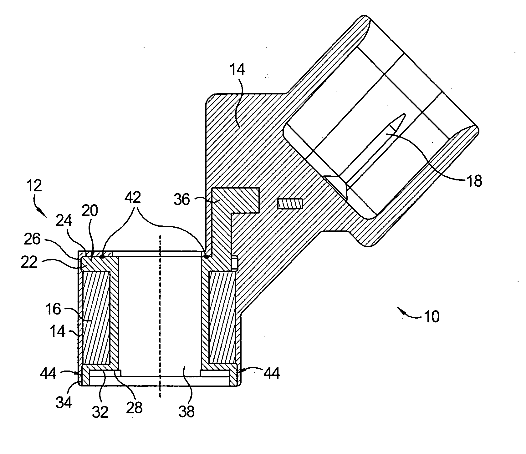
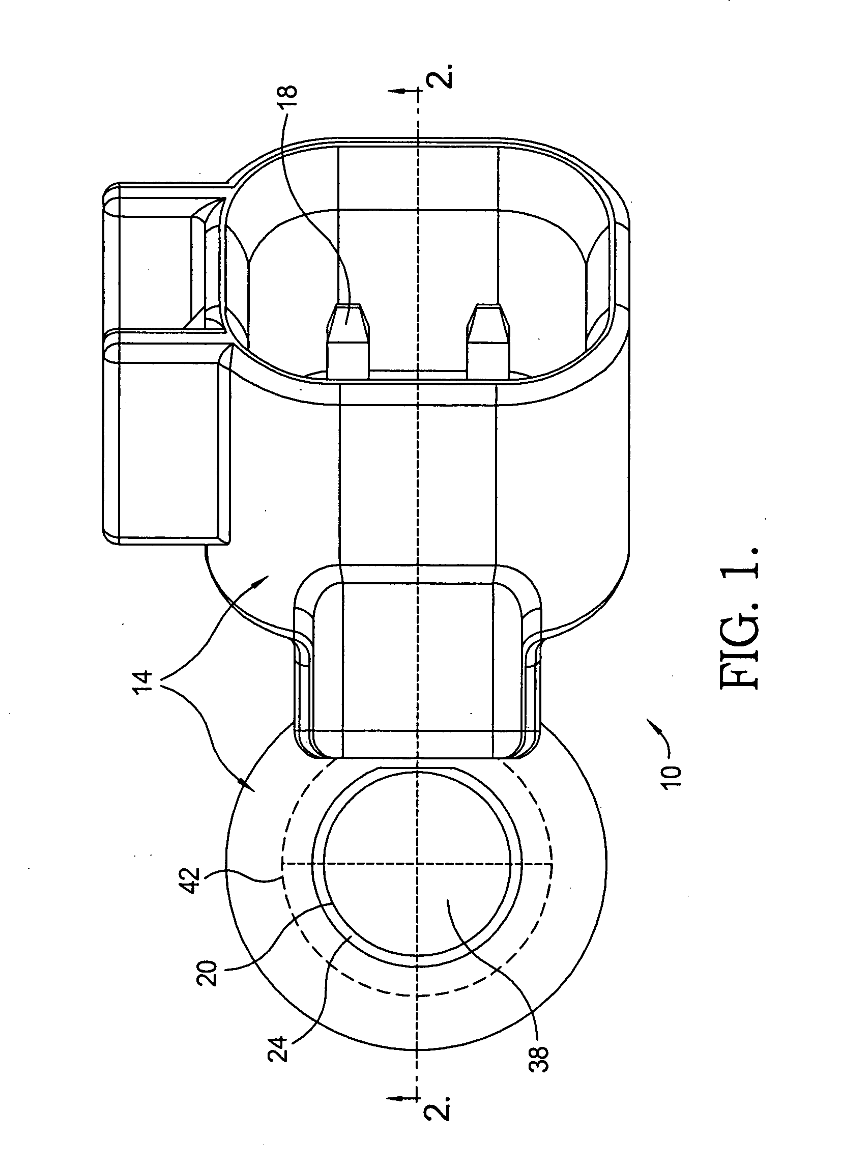
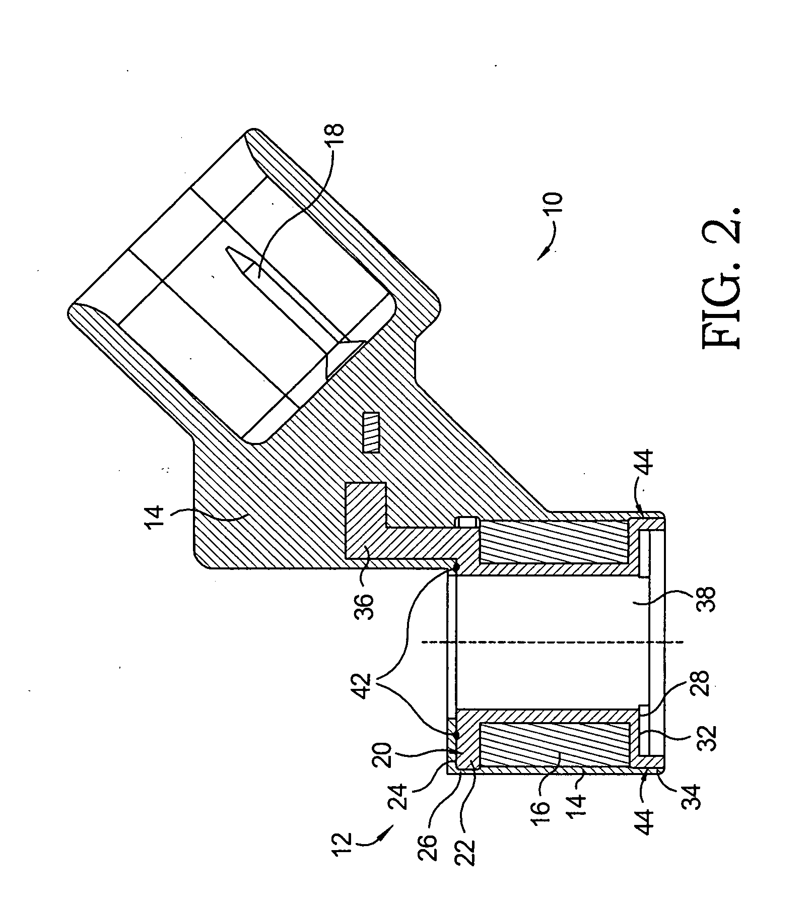
[0015]Referring to FIGS. 1 and 2, a hermetically sealed solenoid coil / connector assembly 10 includes a coil assembly 12 encapsulated by an overmold 14. Coil assembly 12 includes coil wires 16 wound conventionally around a bobbin 20. Bobbin 20 includes a bobbin extension 36 connected to a spade connector 18. Bobbin 20 may further include a top flange 22 having an axial outer face 24 and a side radial face 26 and a bottom flange 28 having an axial outer face 32 and a side radial face 34. Side radial face 26 defines the outer circumferential contour of top flange 22 and side radial face 34 defines the outer circumferential contour of bottom flange 28. Bobbin 20 is provided with a center aperture 38. Center aperture 38 may be appropriately sized for receiving a pole piece. Solenoid coil / connector assembly 10 may be used, for example, in an assembly of a solenoid actuated fuel injector of an internal combustion engine, in known fashion that need not be further elaborated herein.

[0016]Ove...


PUM


Abstract

A solenoid coil / connector assembly includes a coil assembly having coil wires wound around a bobbin, an overmold encapsulating the coil assembly, and a plurality of seals formed between the bobbin and the overmold using laser light, the seals hermetically sealing the coil wires. By using a laser welding process for plastic materials directed at an internal interface between the bobbin and overmold the coil wires become hermetically sealed and moisture is thus prevented from gaining access to coil wires during use of the solenoid coil / connector assembly.

Description

TECHNICAL FIELD[0001]The present invention relates to electric solenoid actuators; more particularly, to solenoids for fuel injectors of internal combustion engines; and most particularly, to a hermetically sealed solenoid coil / connector assembly and a method for hermetically sealing electrical components of a fuel injector solenoid.BACKGROUND OF THE INVENTION[0002]Fuel injectors for internal combustion engines are well known. A typical solenoid actuated fuel injector incorporates a metering poppet valve, a linear solenoid assembly for actuating the valve, and a plastic overmold for isolating the electrical components, such as the wire-wound bobbin of the solenoid assembly, from moisture and dirt. Overmolding a wound bobbin is a known form of protecting coil wires in fuel injectors and other solenoid actuated devices. In the prior art, it has proved difficult to provide a reliable hermetic seal between the wire-wound bobbin and the overmold. But sealing the wire-wound bobbin for pro...

Claims


Application Information

Patent Timeline
Patent Type & Authority Applications(United States)
IPC IPC(8): H01R4/58
CPCH01F7/06H01F2007/062H01F41/127H01F7/128
Inventor HENRY, JAMES P.DEANGELIS, GARY J.
Owner DELPHI TECH INC
Why Eureka
Try Eureka