Image processing apparatus and computer program product

a technology of image processing and computer program, which is applied in the direction of instruments, tomography, ultrasonic/sonic/infrasonic diagnostics, etc., can solve the problems of three-dimensional information about blood flow three-dimensional information about histology not being displayed in a format suitable for diagnosis,

Active Publication Date: 2009-11-26
TOSHIBA MEDICAL SYST CORP
View PDF12 Cites 97 Cited by
  • Summary
  • Abstract
  • Description
  • Claims
  • Application Information

AI Technical Summary

Benefits of technology

[0015]According to an aspect of the present invention, there is provided an image processing apparatus includes an image creating unit that acquires three-dimensional histology information about tissue inside a subject and three-dimensional fluid information about fluid moving inside the subject both of which are created based on a reflection wave of an ultrasonic wave transmitted to the inside of the subject, creates three-dimensional particle information converted from the three-dimensio

Problems solved by technology

According to the above conventional technology, there is a problem that a blood flow cannot be displayed in three dimensions in a format suitable for diagnosis.
As described above, according to the conventional technology, although a turbulent bloo

Method used


Image

  • Image processing apparatus and computer program product
  • Image processing apparatus and computer program product
  • Image processing apparatus and computer program product

Examples


first embodiment

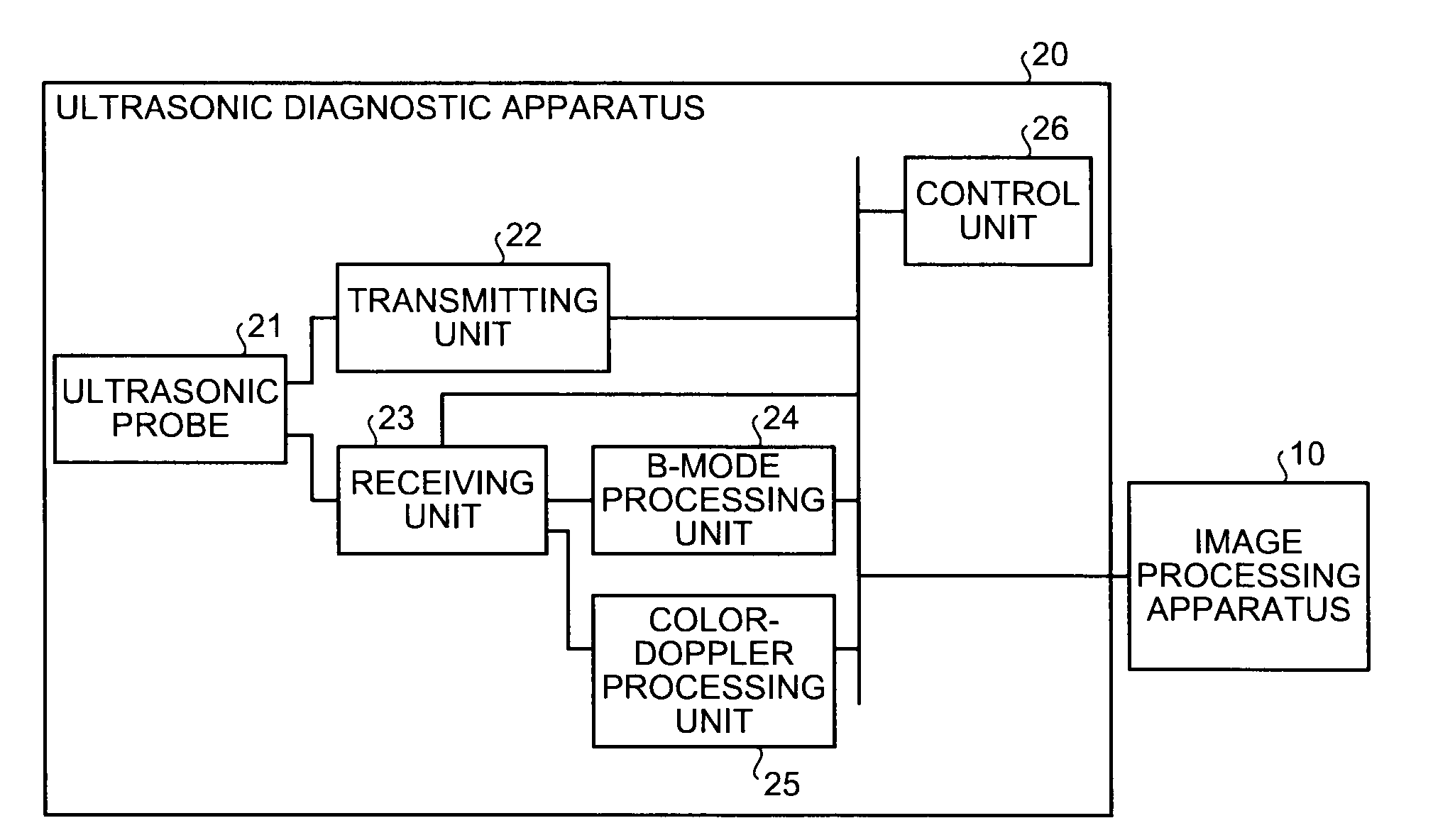
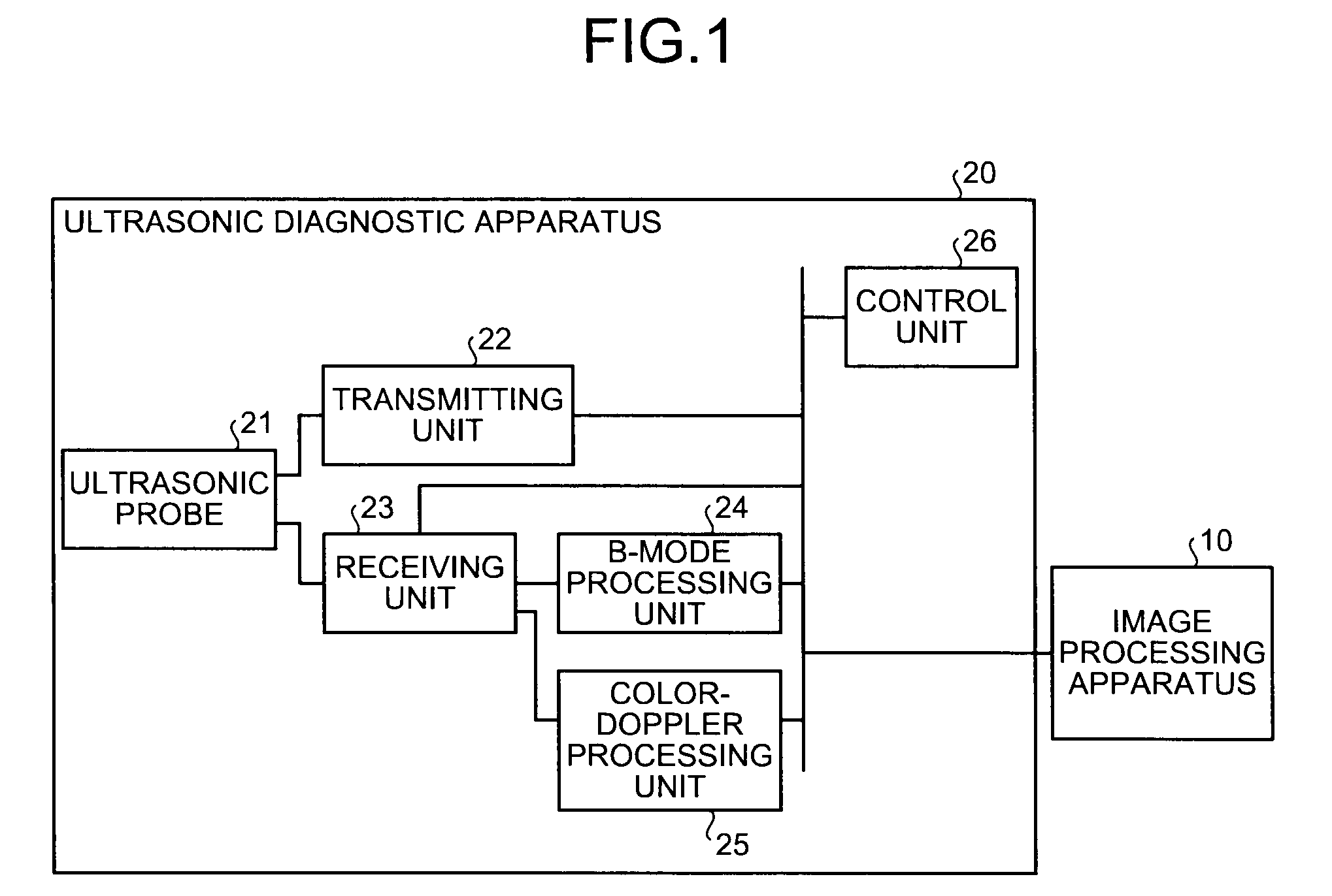
[0032]As shown in FIG. 1, an ultrasonic diagnostic apparatus 20 to be connected to the image processing apparatus includes an ultrasonic probe 21, a transmitting unit 22, a receiving unit 23, a B-mode processing unit 24, a color-Doppler processing unit 25, and a control unit 26.

[0033]The ultrasonic probe 21 is a two-dimensional array transducer ultrasonic probe that includes built-in ultrasonic transducers arranged in matrix, transmits a ultrasonic wave generated by the ultrasonic transducers into the inside of a subject, and receives a reflected wave from internal tissue of the subject, thereby scanning three-dimensionally the inside of the subject.

[0034]The transmitting unit 22 is connected to the ultrasonic probe 21, generates a high-voltage pulse on each predetermined delay time in accordance with the control of the control unit 26, which will be described later, and applies the generated high-voltage pulse to the ultrasonic transducers built-in the ultrasonic probe 21 in order...

second embodiment

[0107]As described above, a composite image can be created through one time of volume rendering, so that display processing of the composite image can be quickly performed.

[0108]Although the first embodiment is explained above in a case where three-dimensional tissue data is displayed by creating a three-dimensional image by volume rendering, the present invention is not limited to this, and can be applied to a case of creating and displaying a cross-sectional tissue image corresponding to a certain cross section in the three-dimensional tissue data.

[0109]Sometimes histology of a portion other than the heart and an embryo (for example, a tumor portion in the liver) cannot be expressed precisely in three-dimensional structure by volume rendering in some cases. In such case, the use of a Multi Planar Reformat (MPR) image is suitable as an image that depicts histology.

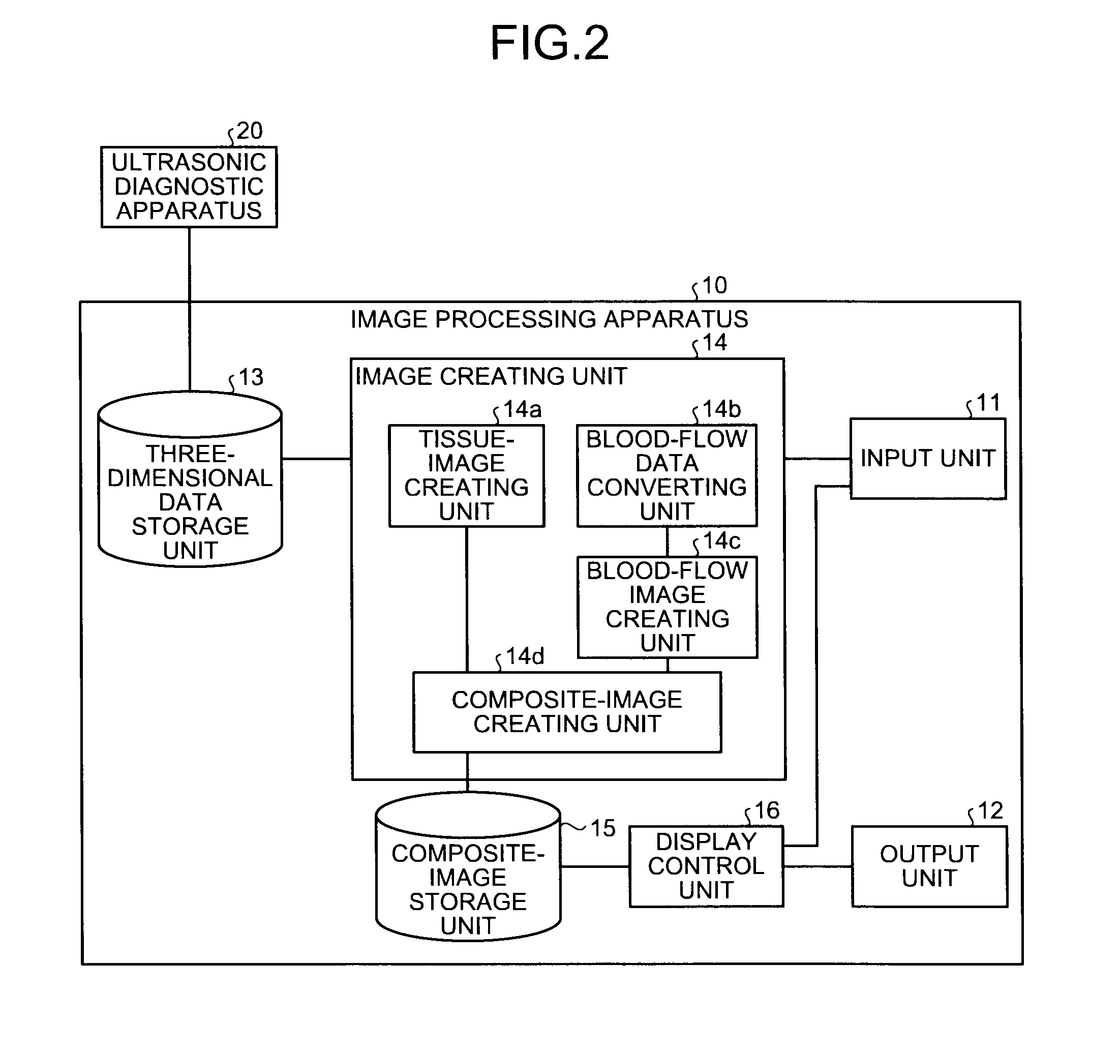
[0110]The tissue-image creating unit 14a creates an MPR image corresponding to a cross section received from the opera...

third embodiment

[0116]Specifically, as shown in FIG. 12, the blood-flow data converting unit 14b determines whether or not to display (display / non-display) three-dimensional blood-flow data (three-dimensional information about a blood flow having depth) on each pixel of a composite image in accordance with random numbers that spatially and temporally vary.

[0117]By determining display / non-display by using random numbers that spatially and temporally vary, the blood-flow data converting unit 14b according to the third embodiment creates three-dimensional particle data converted with scattered particles from the three-dimensional blood-flow data, similarly to the three-dimensional particle data explained in the first and second embodiments. Moreover, by using random numbers that vary not only spatially but also temporally, the blood-flow data converting unit 14b according to the third embodiment creates the three-dimensional particle data that particles shift along time sequence.

[0118]The shape of a ...


PUM


Abstract

A tissue-image creating unit creates a tissue image including depth values by volume rendering from three-dimensional tissue data stored in a three-dimensional data storage unit. A blood-flow data converting unit scatters a blood flow in three-dimensional blood-flow data stored in the three-dimensional data storage unit into particles, and converts the three-dimensional blood-flow data into three-dimensional particle data. A blood-flow image creating unit creates a blood-flow image including depth values from the three-dimensional particle data. A composite-image creating unit then creates a composite image by coordinating the order of rendering particles and tissue based on the depth values of respective pixels included in the tissue image and the depth values of respective particles included in the blood-flow image. A display control unit then controls display of the composite image so as to be displayed in order onto a monitor included in an output unit.

Description

CROSS-REFERENCE TO RELATED APPLICATIONS[0001]This application is based upon and claims the benefit of priority from the prior Japanese Patent Application No. 2008-131834, filed on May 20, 2008; the entire contents of which are incorporated herein by reference.BACKGROUND OF THE INVENTION[0002]1. Field of the Invention[0003]The present invention relates to an image processing apparatus and a computer program product.[0004]2. Description of the Related Art[0005]Conventionally, an ultrasonic diagnostic apparatus is used in a medical practice of today for an examination of and a diagnosis on various living body tissues, such as a heart, a liver, a kidney, and a mammary gland, as an apparatus that has advantages, such as simple to operate, noninvasive, and without risk of radiation exposure, compared with other medical image diagnostic apparatuses, for example, an X-ray diagnostic apparatus, and an X-ray Computed Tomography (CT) apparatus.[0006]An ultrasonic diagnostic apparatus transmits...

Claims


Application Information

Patent Timeline
IPC IPC(8): A61B8/14G06K9/00
CPCA61B8/06A61B8/13G06T19/00A61B8/483G06T15/08G06T2210/24G06T2210/41
Inventor SATO, TAKESHI
Owner TOSHIBA MEDICAL SYST CORP
Why Eureka
Try Eureka