Plungers for intraocular lens injectors

a technology of injectors and plungers, which is applied in the field of plungers, can solve the problems of increasing the force required to push the iol, affecting the dynamics, and the push rod riding over the iol, and achieves accurate control and widening the tolerance

Active Publication Date: 2009-11-26
AMO REGIONAL HLDG
View PDF3 Cites 97 Cited by
  • Summary
  • Abstract
  • Description
  • Claims
  • Application Information

AI Technical Summary

Benefits of technology

[0010]One aspect of the present invention is a plunger for an IOL injector that can flex elastically, vertically and / or laterally, and is guided both vertically and laterally under controlled pre-tension. Because of this, the plunger position can be accurately controlled in that the pre-tension keeps the plunger pressed against the guides independent of slight misalignments arising from the manufacturing or assembly processes. As a result, tolerances can be widened and lateral play between the plunger and its guides are eliminated by the pre-tension.

Problems solved by technology

A cataract is a clouding of the eye's lens that impairs a person's vision and, if left untreated, causes blindness.
This increases the force required to push the IOL through the small cartridge lumen, and impacts on the dynamics between the plunger and the IOL.
Even with the introduction of a viscoelastic medium therebetween, the forces required to push the IOL against friction through the cartridge sometimes result in the push rod riding over the IOL, pinning one of the haptics against the inner lumen of the cartridge, or damaging to the trailing edge of the IOL.
Moreover, the IOL is deformable so the point where it is engaged may shift if the push rod does not have sufficient lateral stiffness.
Likewise, the deformed shape of the IOL may result in a reaction force on the plunger with a force component in a lateral direction that displaces the push rod, causing it to bypass the IOL.
Although one solution is to stiffen the push rod by increasing its cross-section, and reducing its length, these are not practical modifications as they run counter to the desire for a small and often elongated cartridge lumen.

Method used


Image

  • Plungers for intraocular lens injectors
  • Plungers for intraocular lens injectors
  • Plungers for intraocular lens injectors

Examples


Embodiment Construction

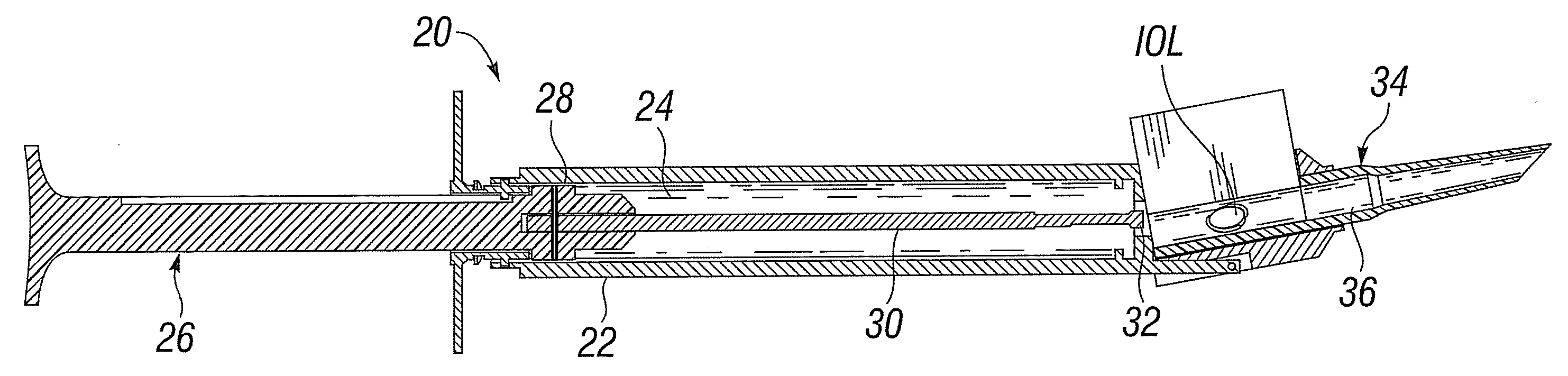
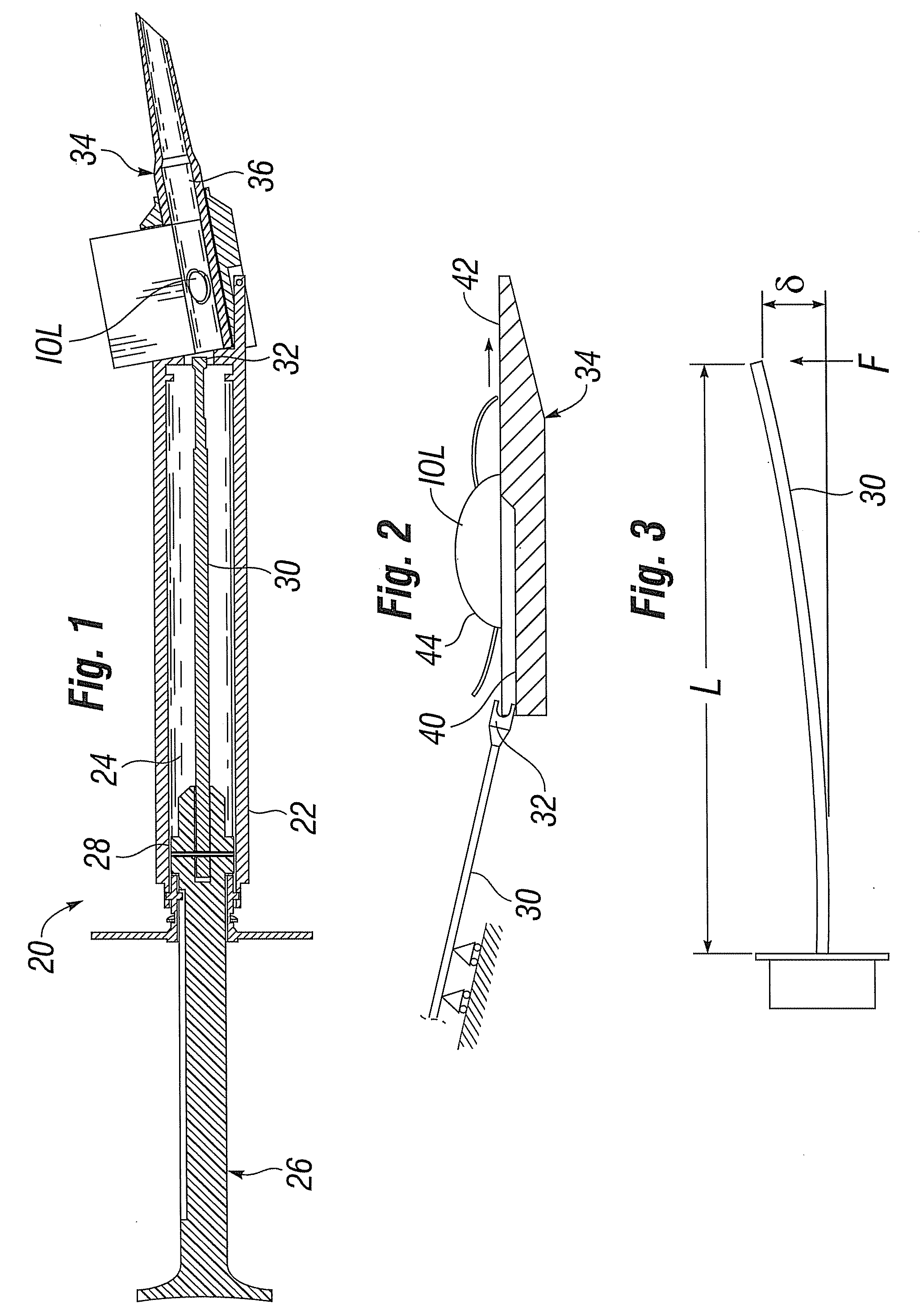
[0039]The present invention facilitates the process of delivering an intraocular lens (IOL) into a patient's eye using an injector. The IOL is typically implanted using an injector that rolls, folds, or otherwise configures the lens for delivery through a small incision in the eye in a way that reduces trauma and expedites post-surgery healing. The IOL is stored separately and transferred to an injector or cartridge just prior to delivery. The injector or injector / cartridge is used in a manner like a hypodermic needle with the IOL being injected into the eye through a delivery tube. The injector, cartridge and / or delivery tube are first partially filled with a liquid or gel lubricating agent, for example a viscoelastic material.

[0040]FIG. 1 is a longitudinal sectional view of an insertion system 20 according to an embodiment of the invention. The insertion system 20 comprises an injector 22 defining and inner bore 24 within which reciprocates a plunger 26 having a piston 28 on the d...


PUM


Abstract

An intraocular lens (IOL) injector for delivering an IOL into an eye of a patient. The injector includes an IOL load chamber and connected delivery tube, and a push rod for urging the IOL through the delivery tube and out of a distal tip thereof. The push rod is guided and biased against one side of the injector load chamber. The injector may include an inflatable pusher for urging the IOL through the delivery tube and out of a distal tip thereof. The inflatable pusher has a proximal end that may be open to an internal cavity of the injector, wherein a plunger movable in the injector cavity forces fluid such as air or saline into the pusher. A distal end of the pusher may be forked to capture a trailing end of the IOL, or may have a bulbous configuration to ensure the pusher does not pass the IOL.

Description

FIELD OF THE INVENTION[0001]The present invention relates to systems and methods for delivering an intraocular lens (IOL) into an eye through an injector / cartridge and, more particularly, to plungers for urging an IOL through an injector / cartridge.BACKGROUND OF THE INVENTION[0002]It is estimated that 73% of Americans between the ages of 65 to 74 get cataracts. A cataract is a clouding of the eye's lens that impairs a person's vision and, if left untreated, causes blindness. As a result, each year approximately 1.4 million people in the United States alone undergo cataract surgery, whereby the clouded natural crystalline lens is removed and replaced with an intraocular lens (IOL) implant.[0003]Surgeons implant IOLs not only as a replacement for the natural crystalline lens but also to alter the optical properties of (provide vision correction to) an eye in which the natural lens remains. IOLs often include an optically clear disk-like optic of about 6 mm in diameter, and preferably a...

Claims


Application Information

Patent Timeline
Patent Type & Authority Applications(United States)
IPC IPC(8): A61F9/007
CPCA61F2/167A61F2/1664
Inventor BOGAERT, THEOPHILUSCATLIN, SCOTT J.
Owner AMO REGIONAL HLDG
Why Eureka
Try Eureka