Vehicle control apparatus

a technology of vehicle control and control device, which is applied in the direction of underwater vessels, non-deflectable wheel steering, special data processing applications, etc., can solve the problems of reducing the steering feel and the possibility of excessive service current in this process, and achieves good steering feel, inhibiting the occurrence of excessive service current, and good steering feel.

Active Publication Date: 2009-11-26
JTEKT CORP
View PDF15 Cites 11 Cited by
  • Summary
  • Abstract
  • Description
  • Claims
  • Application Information

AI Technical Summary

Benefits of technology

[0014]Thus, where the limiting processing that leads to the reduction in motor output is performed rapidly to obtain the effect quickly, the resultant fluctuations of assist force can degrade the steering feel. Therefore, it is desirable that the limiting value be reduced gradually, but the problem resulting therefrom is that the possibility of the excessive service current occurring in this process rises. However, with the above-described configuration, the limiting processing is completed before the cranking is started, thereby making it possible to avoid the occurrence of such a problem. As a result, the application of an assist force with an EPS device can be continued and good steering feel can be maintained even during cranking, while inhibiting the occurrence of excessive service current.
[0015]In the first or second aspect, the second control unit may continuously reduce the limit value when the engine is stopped. With the above-described configuration, in a case where the power source voltage decreases because of deterioration of the power source or the like, the excessive service current can occur even when no ...

Problems solved by technology

Thus, where the limiting processing that leads to the reduction in motor output is performed rapidly to obtain the effect quickly, the resultant fluctuations of assist force can degrade the steering...

Method used


Image

  • Vehicle control apparatus
  • Vehicle control apparatus
  • Vehicle control apparatus

Examples


Embodiment Construction

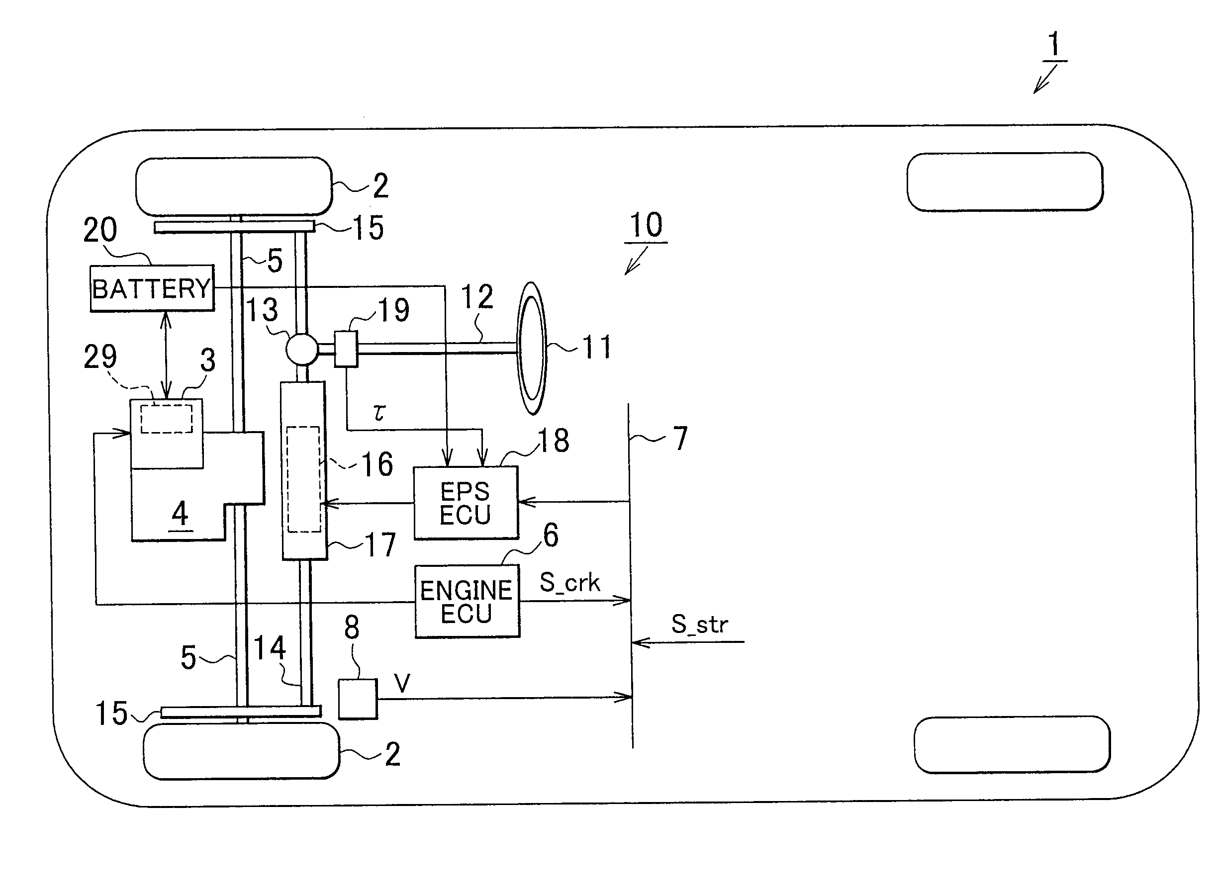
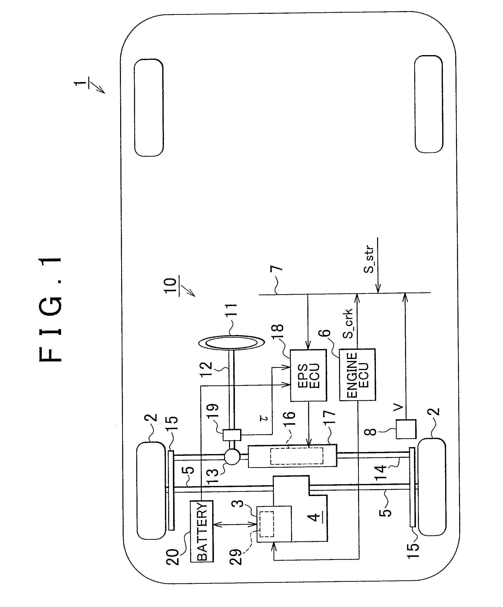
[0023]One embodiment that specifies the invention will be described below with reference to the drawings. As shown in FIG. 1, a vehicle 1 of the embodiment is a car in which front wheels 2 are driven wheels. A pair of front axles 5 are linked to a transaxle 4 assembled with an engine 3, and drive power of the engine 3 is transmitted to the front wheels 2, which are the driven wheels, via the front axles 5. In the embodiment, an engine control unit (ECU) 6 for the engine is connected to the engine 3 that serves as the drive source, and a vehicle speed V detected by a vehicle speed sensor 8, a speed of each wheel, an accelerator depression amount, and an engine start signal S_str are inputted in the engine ECU 6 via an in-vehicle network (CAN: Controller Area Network) 7. Furthermore, in the embodiment, the engine ECU 6 that functions as a first control unit is connected via the in-vehicle network 7 to an electric power steering electronic control unit (EPSECU) 18 that functions as the...


PUM


Abstract

In a case where an engine ECU determines that the engine is started (restarted), the engine ECU notifies an EPSECU that cranking is to be performed to start the engine before performing the cranking. When such a notification is received, the EPSECU gradually reduces a current command limit value I*_lim and a boost voltage limit value Vbp_lim before the cranking is started.

Description

INCORPORATION BY REFERENCE[0001]The disclosure of Japanese Patent Application No. 2008-136863 filed on May 26, 2009 including the specification, drawings and abstract is incorporated herein by reference in its entirety.BACKGROUND OF THE INVENTION[0002]1. Field of the Invention[0003]The invention relates to a vehicle control apparatus that controls the operation of a vehicle engine and an electric power steering (EPS) device.[0004]2. Description of the Related Art[0005]An EPS device using a motor as a drive source has been conventionally used as a power steering device for a vehicle, and because such as a device has a large number of advantages, such as a high degree of layout freedom and small energy consumption, the use thereof has recently expanded to a wide range of vehicle types.[0006]A power source (battery) of such an EPS also serves as a power source of a cell motor that is used for cranking when the engine is started. As a result, the application of an assist force with the ...

Claims


Application Information

Patent Timeline
IPC IPC(8): F02D41/06
CPCF02N11/0814B62D5/046
Inventor NAKAI, TOMOYA
Owner JTEKT CORP
Why Eureka
Try Eureka