Collision avoidance method and system using stereo vision and radar sensor fusion

a radar sensor and stereo vision technology, applied in the field of collision avoidance systems, can solve the problems of large azimuth angular error or noise, poor azimuth angular resolution of radar sensor 16/b>, and measurement capability

Inactive Publication Date: 2009-11-26
SARNOFF CORP
View PDF5 Cites 263 Cited by
  • Summary
  • Abstract
  • Description
  • Claims
  • Application Information

AI Technical Summary

Benefits of technology

[0015]The depth sensor may be at least one of a stereo vision system comprising one of a 3D stereo camera and two monocular cameras calibrated to each other, an infrared imaging systems, light detection and ranging (LIDAR), a line scanner, a line laser scanner, Sonar, and Light Amplification for Detection and Ranging (LADAR). The position of the threat object may be fed to a collision avoidance implementation system. The position of the threat object may be the location, size, pose and motion parameters of the threat object. The host object and the threat object may be vehicles.
[0016]Although embodiments of the present invention relate to the alignment of radar sensor and stereo vision sensor observations, other embodiments of the present invention relate to aligning two possibly disparate sets of 3D points. For example, according to another embodiment ...

Problems solved by technology

Unfortunately, the radar sensor 16 provides poor azimuth angular (lateral) resolution, as indicated by radar error bounds 18.
Large azimuth angular error or noise are typically attributed to limitations of the measurement capabilities of the radar sensor 16 and to a non-fixing reflection point on the rear part of the threat vehicle 12.
Moreover, although laser scanning radar can detect the occupying area of the threat vehicle 12, it is prohibitively expensive for automotive applications.
In addition, affordable automotive laser detection and ranging (LADAR) can only reliably detect reflectors located on...

Method used


Image

  • Collision avoidance method and system using stereo vision and radar sensor fusion
  • Collision avoidance method and system using stereo vision and radar sensor fusion
  • Collision avoidance method and system using stereo vision and radar sensor fusion

Examples


Embodiment Construction

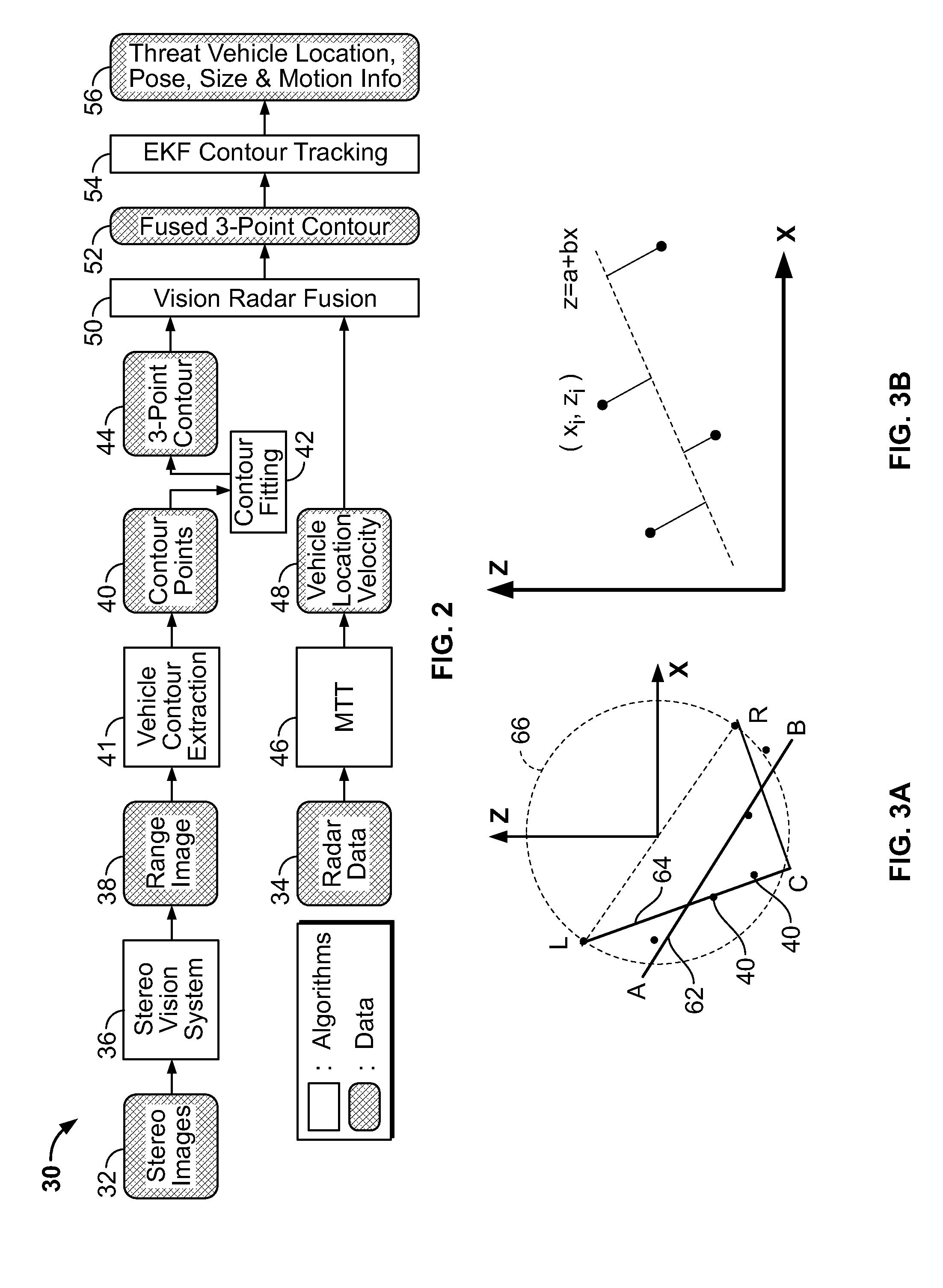
[0031]FIG. 2 presents a block diagram of a depth-radar fusion system 30 and related process, according to an illustrative embodiment of the present invention. According to an embodiment of the present invention, the inputs of the depth-radar fusion system 30 include left and right stereo images 32 generated by a single stereo 3D camera, or, alternatively, a pair of monocular cameras whose respective positions are calibrated to each other. According to an embodiment of the present invention, the stereo camera is mounted on a host object, which may be, but is not limited to, a host vehicle. The inputs of the depth-radar fusion system 30 further include radar data 34, comprising ranges and azimuthes of radar targets, and generated by any suitable radar sensor / system known in the art.

[0032]A stereo vision module 36 accepts the stereo images 32 and outputs a range image 38 associated with the threat object, which comprise a plurality of at least one of 1, 2, or 3-dimensional depth values...


PUM


Abstract

A system and method for fusing depth and radar data to estimate at least a position of a threat object relative to a host object is disclosed. At least one contour is fitted to a plurality of contour points corresponding to the plurality of depth values corresponding to a threat object. A depth closest point is identified on the at least one contour relative to the host object. A radar target is selected based on information associated with the depth closest point on the at least one contour. The at least one contour is fused with radar data associated with the selected radar target based on the depth closest point to produce a fused contour. Advantageously, the position of the threat object relative to the host object is estimated based on the fused contour. More generally, a method is provided for aligns two possibly disparate sets of 3D points.

Description

CROSS-REFERENCE TO RELATED APPLICATIONS[0001]This application claims the benefit of U.S. provisional patent application No. 61 / 039,298 filed Mar. 25, 2008, the disclosure of which is incorporated herein by reference in its entirety.GOVERNMENT RIGHTS IN THIS INVENTION[0002]This invention was made with U.S. government support under contract number 70NANB4H3044. The U.S. government has certain rights in this invention.FIELD OF THE INVENTION[0003]The present invention relates generally to collision avoidance systems, and more particularly, to a method and system for estimating the position and motion information of a threat vehicle by fusing vision and radar sensor observations of 3D points.BACKGROUND OF THE INVENTION[0004]Collision avoidance systems for automotive navigation have emerged as an increasingly important safety feature in today's automobiles. A specific class of collision avoidance systems that have generated significant interest of late is advanced driving assistant system...

Claims


Application Information

Patent Timeline
IPC IPC(8): G08G1/16G01S13/08G01S13/00
CPCB60W30/08G01S13/726G01S13/931G01S2013/9375G01S13/862G01S13/865G01S13/867G08G1/16G08G1/165G01S2013/93271
Inventor WU, SHUNGUANGCAMUS, THEODOREPENG, CHANG
Owner SARNOFF CORP
Why Eureka
Try Eureka