Simplified thrust chamber recirculating cooling system

a cooling system and thrust chamber technology, applied in the field of rocket engines, can solve the problems of high-overhead, high cost of fabricators, and the cooling system of thrust chambers

Inactive Publication Date: 2009-12-03
GROTE JAMES ROBERT +1
View PDF6 Cites 24 Cited by
  • Summary
  • Abstract
  • Description
  • Claims
  • Application Information

AI Technical Summary

Problems solved by technology

These types of coolant tubes and flow passages for regeneratively cooled thrust chambers are produced by a small number (perhaps several) of very specialized, high-overhead,...

Method used


Image

  • Simplified thrust chamber recirculating cooling system
  • Simplified thrust chamber recirculating cooling system
  • Simplified thrust chamber recirculating cooling system

Examples


Embodiment Construction

[0022]In the following detailed description, reference is made to the accompanying drawings that form a part hereof, and in which is shown by way of illustration specific implementations which may be practiced. These implementations are described in sufficient detail to enable those skilled in the art to practice the implementations, and it is to be understood that other implementations may be utilized and that logical, mechanical, electrical and other changes may be made without departing from the scope of the implementations. The following detailed description is, therefore, not to be taken in a limiting sense.

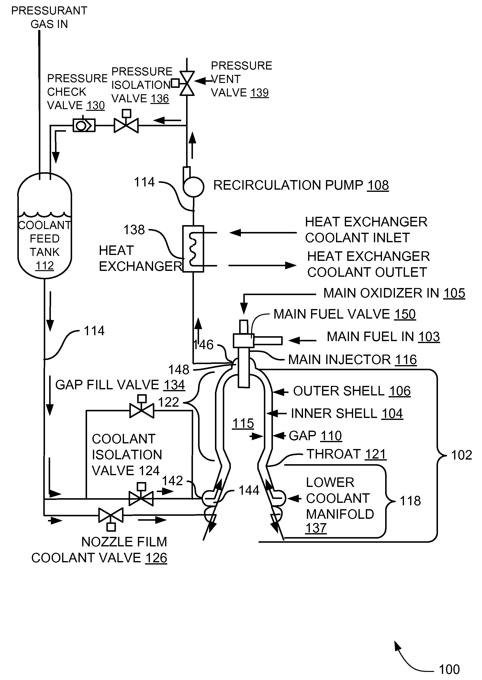
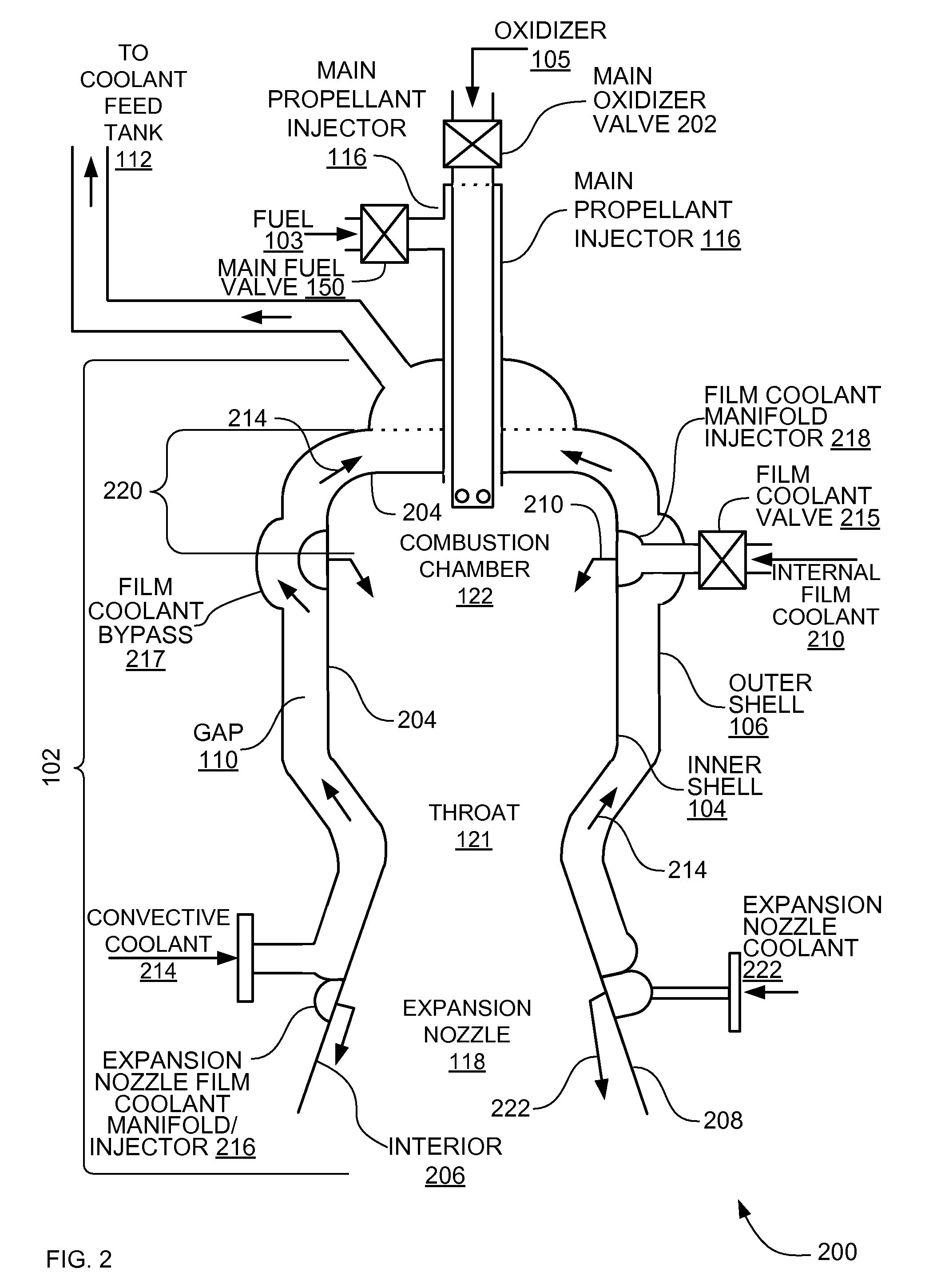
[0023]The systems, methods and apparatus described herein involve low-cost rocket engine technology that can be used to produce liquid propellant rocket engines of a very wide range of thrust sizes or propellant combinations for private, commercial, or government aerospace programs. Such an engine technology provides liquid propellant rocket engines at greatly reduced cost a...


PUM


Abstract

In some aspects a propulsion system includes a thrust chamber having a gap between an inner shell and an outer shell, the inner shell and the outer shell being attached together to form the thrust chamber. The rocket engine also includes a recirculating cooling system operably coupled to the gap in at least two locations and operable to recirculate a convective coolant through the gap.

Description

RELATED APPLICATION[0001]This application claims the benefit of U.S. Provisional Application Ser. No. 60 / 930,373 filed May 15, 2007 under 35 U.S.C. 119(e).FIELD[0002]This invention relates generally to propulsion systems, and more particularly to rocket engines.BACKGROUND[0003]In conventional liquid propellant rocket engines, a main propellant injector sprays liquid propellants into a combustion chamber, where the propellants are burned. The burned propellants expand in an expansion nozzle, where the resulting gases increase in velocity and produce thrust. A thrust chamber encompasses both the combustion chamber and the expansion nozzle.[0004]One of the propellants (usually the fuel) flows through coolant tubes or channels in the thrust chamber. The relatively cool propellant flowing in the coolant tubes or channels cools the thrust chamber and prevents the thrust chamber from failing or melting. These conventional fluid cooled engines are typically called regeneratively cooled engi...

Claims


Application Information

Patent Timeline
IPC IPC(8): F02K99/00
CPCF02K9/64F05D2260/205F05D2260/202
Inventor GROTE, JAMES ROBERTPAVIA, THOMAS CLAYTON
Owner GROTE JAMES ROBERT
Why Eureka
Try Eureka