Automatic pneumatic gripper

a technology of automatic gripper and gripper head, which is applied in the direction of inking apparatus, manufacturing tools, coatings, etc., can solve the problems of uneven thickness of printed image, difficulty in assembling/disassembling squeegee/scraper, etc., and achieve the effect of improving the safety and convenience of assembling/disassembling squeegee/scraper of screen printing machin

Active Publication Date: 2009-12-03
ATMA CHAMP ENTERPRISE
View PDF2 Cites 10 Cited by
  • Summary
  • Abstract
  • Description
  • Claims
  • Application Information

AI Technical Summary

Benefits of technology

[0004]Therefore it is a primary object of the present invention to provide an automatic pneumatic gripper that is applied to a fixing post of a printing head of a screen printing machine for assembling a squeegee / scraper under the fixing post. The automatic pneumatic gripper consists of a pneumatic cylinder with a plunger moving upward / downward by air, disposed on a top surface of a fixing post, two grippers moving horizontally are pivoted on two transverse sides of the pneumatic cylinder, and a plurality of elastic members. An upper part of each gripper is pivoted on the side of the pneumatic cylinder by a pivot so that at least one gripper is pivoted inward to be in a tightly clipped state or pivoted outwards to form a released state. The lower part of the gripper extends downward beyond a bottom surface of the fixing post, and projects inwards to form a hook for hooking with a holding seat of the squeegee / scraper. The elastic members are disposed between the pneumatic cylinder and the gripper correspondingly. By elasticity of these elastic members, the gripper can turn back to original position and become located automatically while pivoting. When the plunger of the pneumatic cylinder protrudes downward and leans against a top surface of the fixing post, the gripper is forced to pivot inward and become closer to each other so that the hook on the lower part of the gripper hooks on the holding seat of the squeegee / scraper and attaches on the bottom surface of the fixing post firmly to form a fastened state. When the plunger of the pneumatic cylinder retracts upward and leaves the top surface of the fixing post, the pneumatic cylinder relatively falls down (moves downward) and the inner side of the gripper is against by the upper part of the fixing post and is pivoted outward to form a released state. Thus the hook on the lower part releases from the holding seat of the squeegee / scraper to form a released state. Thereby, convenience and safety of assembling / disassembling of a squeegee / scraper of a printing head on a screen printing machine are improved.

Problems solved by technology

The difficulties in sleeving / releasing of the clamping member 10 further bring difficulties in assembling / disassembling of the squeegee / scraper 32.
When a longer squeegee31 / scraper 32 is used, thickness of the printed image may be uneven due to uneven force.

Method used


Image

  • Automatic pneumatic gripper
  • Automatic pneumatic gripper
  • Automatic pneumatic gripper

Examples


Embodiment Construction

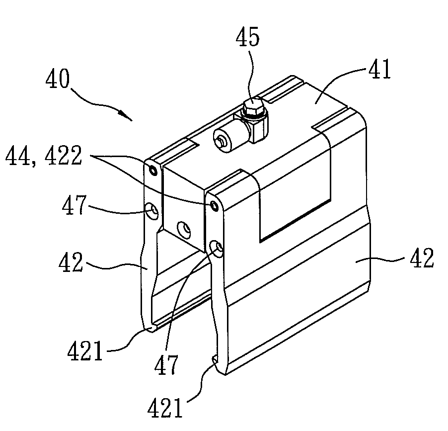
[0020]Refer from FIG. 6 to FIG. 10, an automatic pneumatic gripper 40 is applied to a fixing post of a printing head of a screen printing machine for assembling / disassembling a squeegee 31 / a scraper 32. The automatic pneumatic gripper 40 consists of a pneumatic cylinder 41, two grippers 42 and a plurality of elastic members 43. The pneumatic cylinder 41 is arranged over a fixing post 30 and a gripper 42 moving horizontally is pivoted on two transverse sides of the pneumatic cylinder 41. At least one air source connector 45 is arranged on a top or a side surface of the pneumatic cylinder 41 for connecting compressed air (not shown in figure) so as to drive a plunger 411 moving vertically. Moreover, according to users' needs, the pneumatic cylinder 41 can be a single acting cylinder or a double acting cylinder. An upper part of each gripper 42 is disposed with a pivoting hole 422 for assembling with a pivot 44 which is correspondingly pivoted on two sides of the pneumatic cylinder 41...


PUM


Abstract

An automatic pneumatic gripper applied to a screen printing machine includes a pneumatic cylinder disposed on a top surface of a fixing post and two elastic grippers pivoted on two transverse sides of the pneumatic cylinder respectively. The lower part of two grippers extend downward beyond a bottom surface of the fixing post and projects inwards to form a hook. When a plunger of the pneumatic cylinder protrudes downward and leans against the top surface of the fixing post 30, the two grippers pivot inward, clip and fasten a squeegee / scraper firmly on the fixing post by the hook. When the plunger retracts upward, the pneumatic cylinder falls down relatively falls down so that the two grippers pivot outward, away from each other and the squeegee / scraper is released.

Description

BACKGROUND OF THE INVENTION[0001]The present invention relates to an automatic pneumatic gripper, especially to an automatic pneumatic gripper applied to a fixing post of a screen printing machine for arranging squeegees or scrapers under the fixing post.[0002]Generally, a fixing member is used to assemble and fasten a squeegee / scraper on a fixing post of a printing head on a screen printing machine. Refer from FIG. 1 to FIG. 3, a clamping member 10 formed by a c-shaped clip 11 for clipping on a fixing post 30 of a printing head and a manual-operated bolt 12 threaded on top thereof. A projecting member is disposed on each side of a bottom of the clamping member 10 for clipping a top surface of a squeegee / scraper 32. While being rotated clockwise, the manual-operated bolt 12 moves downward and contacts with the top surface of the fixing rod 30 so that the c-shaped clip 11 relatively moves upward and further drives the top surface of the squeegee / scraper 32 to move upward to be attach...

Claims


Application Information

Patent Timeline
IPC IPC(8): B41F15/14
CPCB41P2215/10B41F15/44
Inventor CHEN, TUNG-CHIN
Owner ATMA CHAMP ENTERPRISE
Why Eureka
Try Eureka