

Intake duct
a technology of intake ducts and ducts, which is applied in the direction of machines/engines, combustion-air/fuel-air treatment, and feed systems, etc., can solve the problems of engine ill effects, and achieve the effect of reducing the noise of intake, and not increasing the parts coun
- Summary
- Abstract
- Description
- Claims
- Application Information
AI Technical Summary
Benefits of technology
Problems solved by technology
Method used
Image

Examples
Embodiment Construction
[0018]Preferred embodiments will be described below with reference to the drawings. It is to be noted that the following embodiments do not necessarily restrict the invention according to the claims and all the combinations of the features of the invention described in the embodiments cannot be indispensable to the means of solution according to the invention.
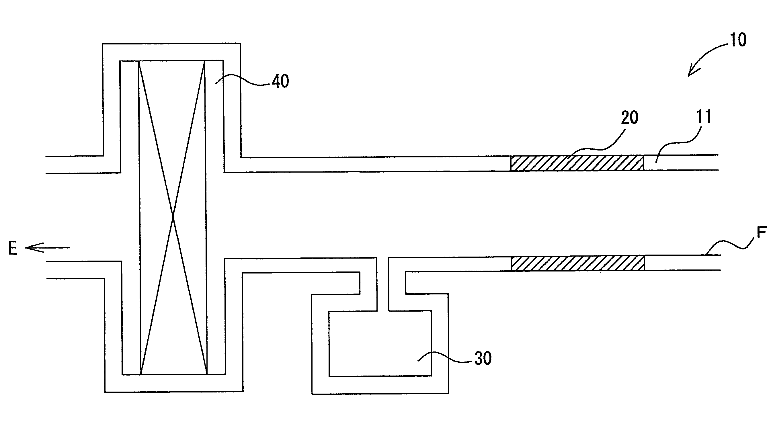
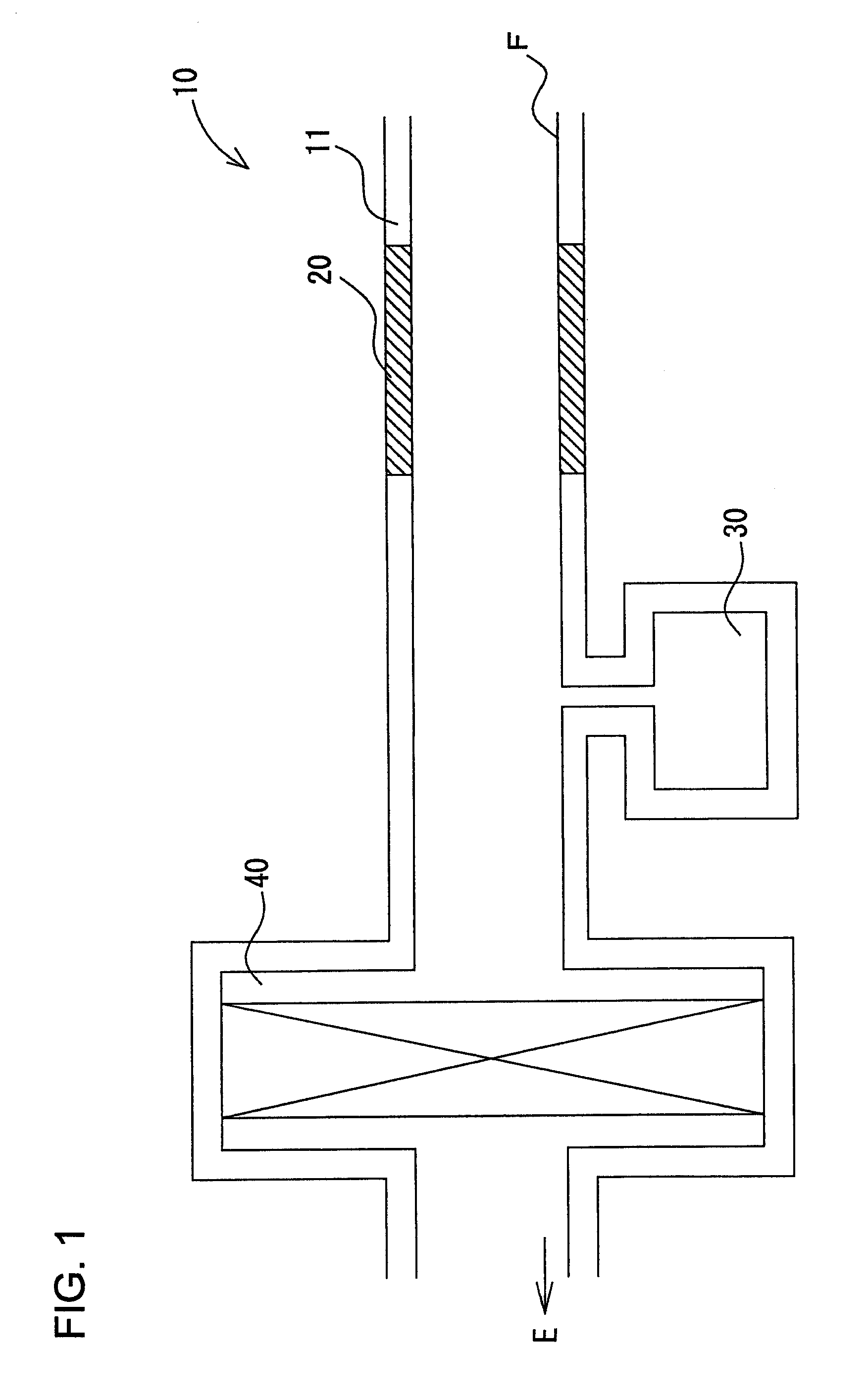
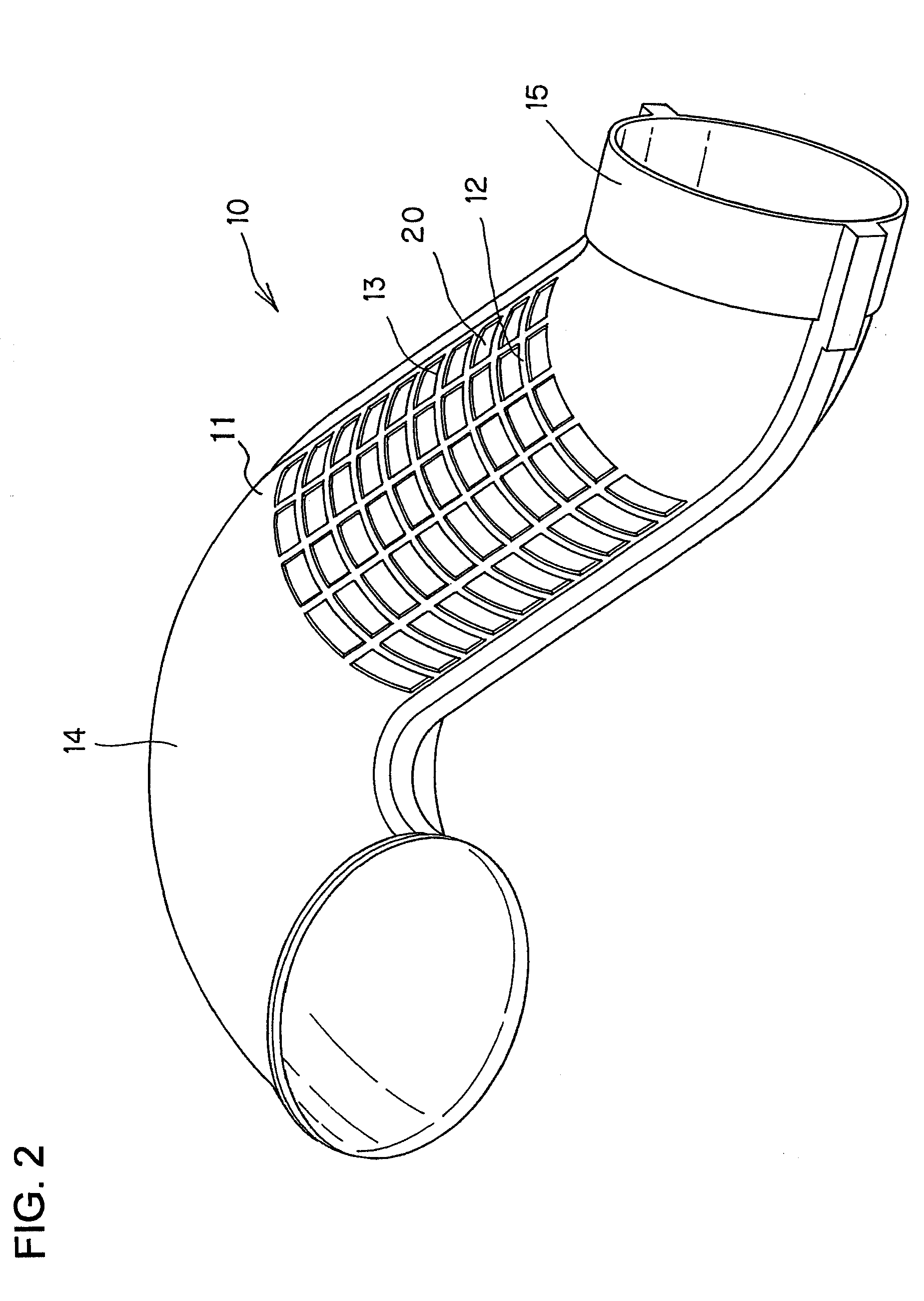
[0019]FIG. 1 is a schematic view showing an intake path of the internal combustion engine, FIG. 2 is a perspective view of an intake duct according to an embodiment of the invention, FIG. 3 is a perspective view of a half cut duct constituting the intake duct of the embodiment, and FIG. 4 is a sectional view in the radial direction of the half cut duct constituting the intake duct of the embodiment.
[0020]As shown in FIG. 1, the intake path of the internal combustion engine includes a resonator 30 connected to the intake duct 10 comprising a tubular duct wall 11, between an intake vent F and an air cleaner 40 of the intake duct....
PUM
 Abstract
Description
Claims
Application Information