Mounting Clamp For A Floor Heating System

a technology for heating systems and clamps, applied in the field of mounting clamps, can solve the problems of frame not having a large tread fare, frame is too fragile for the task, and the clamp is relatively high and slender, so as to improve the effect of mounting clamps

Inactive Publication Date: 2009-12-03
PEDERSEN ASKER HOJLUND +1
View PDF7 Cites 12 Cited by
  • Summary
  • Abstract
  • Description
  • Claims
  • Application Information

AI Technical Summary

Benefits of technology

[0014]In this surprisingly simple manner, a mounting clamp is achieved, which can stand stably on the base without turning over because of the size and the shape of the frame and the foot plate, and which may be snapped on to the reinforcement net in one horizontally extending movement, whereby the wire is caught by the incision and is guided by the guide plates forwards to the seat, where the wire is secured by the seat and the locking pawl in combination.
[0015]The movement of the mounting clamp above the base is controlled and supported by the foot plate and is implemented by pressing on the pressure plate, which is arranged on the rear edge of the frame. Then, the necessary number of clamps may be arranged quickly, and subsequently the heat generator is pressed into position in the means for securing the heat generator by the foot. Further, the reinforcement net and the heat generator are separated, so that the heat generators are not subjected to wear at the tying points.

Problems solved by technology

The mounting clamp is relatively high and slender, and it must be assumed that it may be problematic, to make the heating cells He stably, because the coils are not supported between the clamps, and also because the supporting faces of the clamps are relatively small.
On the face of it, the frame appears to be too fragile for the task, and the frame does not have large tread fare.
The configuration of the clamp does not appear to be expedient, and must be assumed to cause problems in the mounting.
The position of the wire and the distance from the base and to the seat of the wire seem to be insufficient if there is to be room for a reasonable amount of concrete below the net, in order to avoid cracking caused by loading or corrosion.
The work involved with this clamp is not attractive.
It is time consuming and troublesome because the pipe-coils are heavy and very stiff.
The work involved by the laying of the heating coils and tying them firmly to the reinforcement net by strips or metal wire, is cumbersome and time-consuming and involves an extreme strain on the knees and the back, because the coils are to be unrolled and laid while being tied to the reinforcement net.
The rolls are heavy and cumbersome to handle.
In addition, it is a problem to walk on the net which yields and deflects because of the assembly on blocks.
In addition, it may give rise to problems if the coils are tied tightly and firmly to the reinforcement net.
The expansions of the material may then cause leaks on the coils in the areas where they are tied because of the wear against the reinforcement net.

Method used


Image

  • Mounting Clamp For A Floor Heating System
  • Mounting Clamp For A Floor Heating System
  • Mounting Clamp For A Floor Heating System

Examples


Embodiment Construction

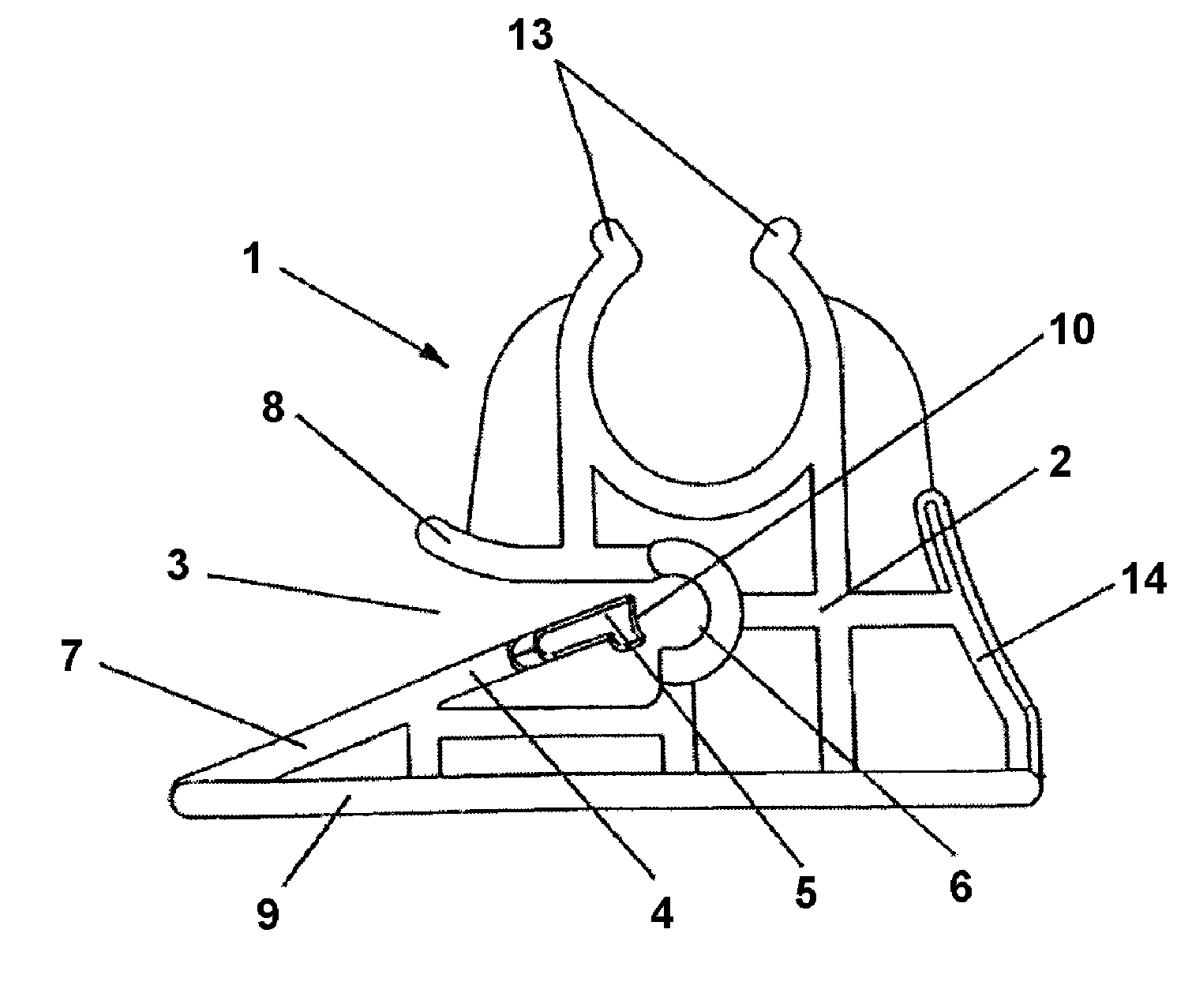
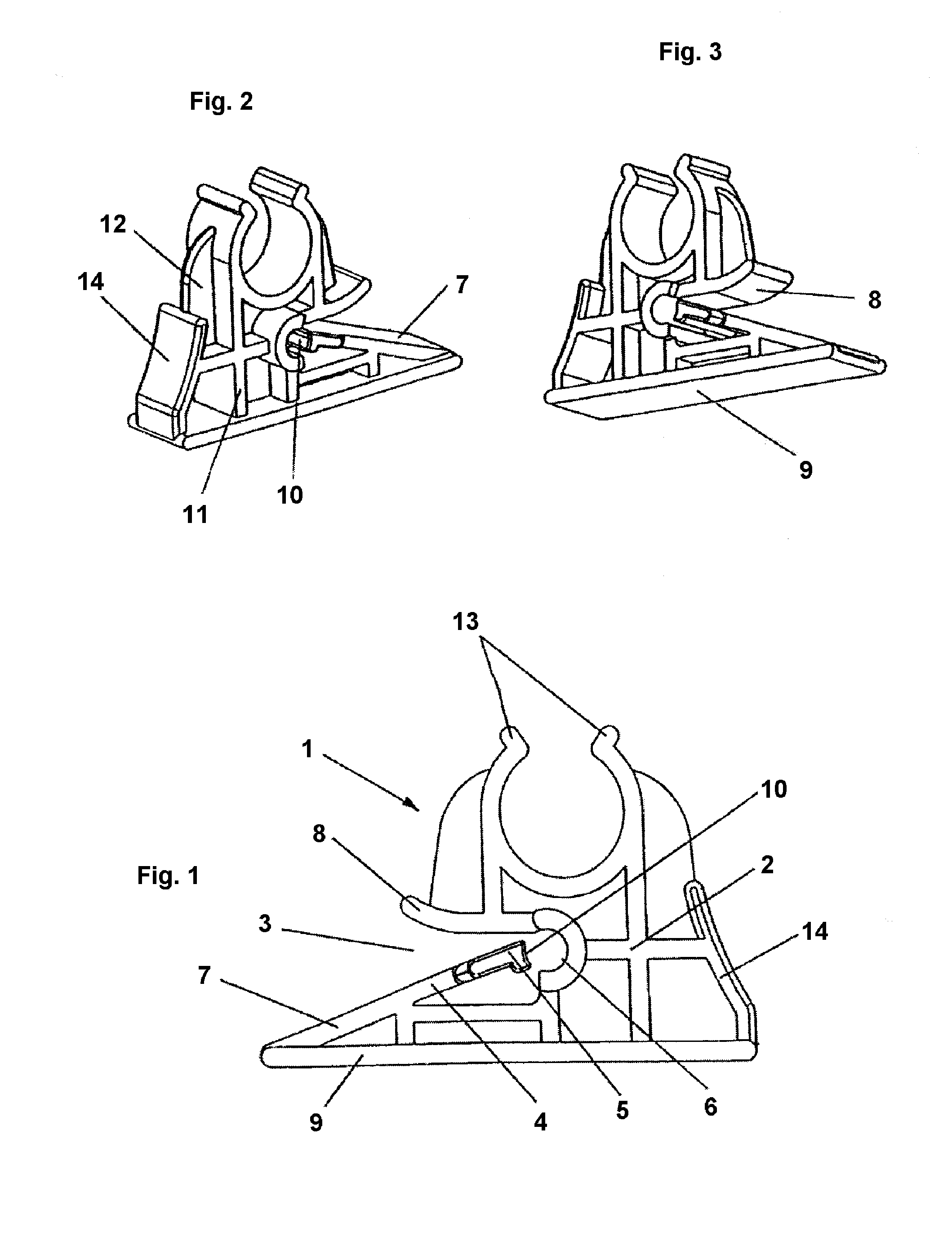
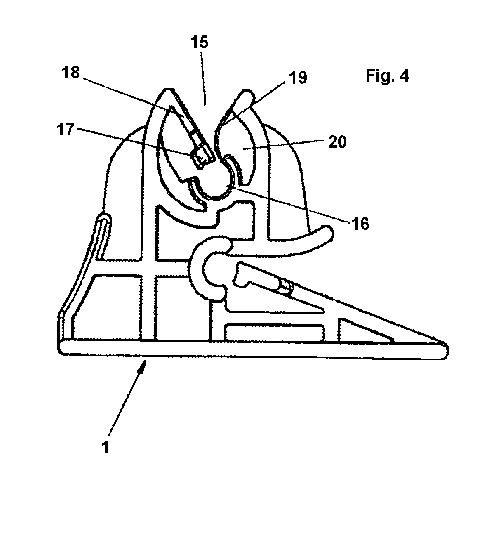
[0027]FIG. 1 shows a side view of the mounting clamp 1 according to the invention. It will be seen in the figure that the mounting clamp is provided with a pipe depression having arms 13, which are configured to grip a pipe or cable-like heat generator. The arms 13 are built together with and placed centrally above the frame 2, which stands on the foot plate 9.

[0028]The frame 2 is provided with a substantially horizontally extending incision 3 for receiving a wire from the reinforcement net. Opposite the incision 3, the frame is additionally equipped with a pressure plate 14 which is used in the mounting of the mounting clamp. The incision 3 is funnel-shaped and is provided with lower and upper guide plates 7, 8, which define the funnel and point inwards toward the centre of the frame to a seat 6 for the wire.

[0029]The lower guide plate 7 extends with a slightly upwardly rising inclination from the front edge of the foot plate 9 at the mouth of the incision 3 and forwards to the sea...


PUM


Abstract

When according to the invention, a mounting clamp (1) for a floor heating system and for mounting on a reinforcement net is constructed such that is comprises a frame (2) on a foot plate (9) as well as means for gripping and securing a pipe or cable-like heat generator to the mounting clamp (1) and to the reinforcement net, and the frame (2) is provided with a means in the form of a substantially horizontally extending incision (3) having a locking pawl (4) for receiving a wire from the reinforcement net, it is ensured that the mounting clamp may be snapped on to the reinforcement net in one movement. When the frame (2) is additionally provided with a means in the form of a funnel (15) having an upwardly directed mouth with guide plates (18,19) and with a locking pawl (17), it may advantageously be used for electrical heating cables.

Description

THE PRIOR ART[0001]The invention relates to a mounting damp, in particular for a floor heating system, and for mounting on a reinforcement net, which comprises a frame, a foot plate as well as means for gripping and securing a pipe or cable-like heat generator to the mounting damp and means for securing the mounting clamp to the reinforcement net, and wherein the means tor gripping and securing the pipe or cable-like heat generator comprise a substantially upwardly extending opening, and wherein the means for securing the mounting clamp to the reinforcement net comprise a substantially horizontally extending Incision, said incision being funnel-shaped and equipped with an upper guide plate and a lower guide plate which are directed inwards toward a seat for a wire, and wherein the lower guide plate extends with e slightly upwardly rising inclination from the front edge of the foot plate at the mouth of the incision and forwards to the seat, and that the incision additionally is equi...

Claims


Application Information

Patent Timeline
Patent Type & Authority Applications(United States)
IPC IPC(8): F16L3/08
CPCF16L3/13Y02B30/26F24D13/02F24D3/141Y02B30/00
Inventor PEDERSEN, ASKER HOJLUNDDEJLIGBJERG, TORBEN
Owner PEDERSEN ASKER HOJLUND
Why Eureka
Try Eureka