Method to determine the design of a basic magnet of a magnetic resonance apparatus with at least one gradient coil system

a technology of gradient coil and basic magnet, which is applied in the direction of wave based measurement system, using reradiation, instruments, etc., can solve the problems of image artifacts and eddy current losses, compromises in specifications,

Active Publication Date: 2009-12-03
SIEMENS HEALTHCARE GMBH
View PDF7 Cites 0 Cited by
  • Summary
  • Abstract
  • Description
  • Claims
  • Application Information

AI Technical Summary

Benefits of technology

[0007]An object of the present invention is to prov

Problems solved by technology

These oscillations can cause noise as well as image artifacts and eddy current losses in the structure of the magnet or the cryostat fashioned with superconducting coils, with the result of a vaporization o

Method used


Image

  • Method to determine the design of a basic magnet of a magnetic resonance apparatus with at least one gradient coil system
  • Method to determine the design of a basic magnet of a magnetic resonance apparatus with at least one gradient coil system
  • Method to determine the design of a basic magnet of a magnetic resonance apparatus with at least one gradient coil system

Examples


Embodiment Construction

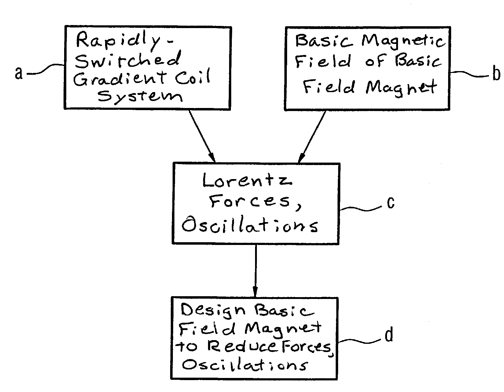
[0036]The basic steps for design determination of a basic field magnet of a magnetic resonance system in a method according to the invention are shown in FIG. 1. The basic design concerns a method in which both the design of the basic magnet and the design of the gradient coil system are determined.

[0037]Block a symbolizes that the gradient coil system of a magnetic resonance apparatus is subjected to fast switching processes.

[0038]Block b indicates that the gradient coil system with the fast switching processes according to block a is located in a strong magnetic field of a basic field magnet. Lorentz forces that act on the gradient coil system and excite this to oscillations thereby result, as indicated by the block c. These Lorentz forces or, respectively, oscillations according to block c are now taken into account for the design of the basic magnet in the method according to the invention, as is indicated by the block d. Furthermore, they are considered as well in the design of...


PUM


Abstract

The method for determination of the design of the basic magnet of a magnetic resonance apparatus with at least one gradient coil system, the design of the basic magnet is determined by taking into consideration forces acting on the at least one gradient coil system that may lead to vibrations of the gradient coil system due to switching processes of the gradient coil system in the field of the basic magnet.

Description

BACKGROUND OF THE INVENTION[0001]1. Field of the Invention[0002]The present invention concerns a method to determine the design of a basic magnet of a magnetic resonance apparatus with at least one gradient coil system.[0003]2. Description of the Prior Art[0004]In magnetic resonance apparatuses that serve to generate image exposures of structures inside the body, a system of gradient magnetic fields is superimposed on the basic magnetic field for spatial coding of the image information. For this purpose, high currents are applied and removed again within the shortest possible time in the gradient coils serving for field generation. The conductors of the gradient coils are subjected to strong forces due to this rapid switching of the gradient coils in the strong magnetic field of the basic magnet.[0005]The Lorentz forces that act on electrical charges in electromagnetic fields additively combine to produce large net forces. The forces accordingly acting on the gradient coil generate ...

Claims


Application Information

Patent Timeline
IPC IPC(8): H01F5/00
CPCG01R33/288G01R33/3854G01R33/3815G01R33/381
Inventor DIETZ, PETERHUTTON, GRAHAMKRUG, ANDREASENDT, AXEL VOM
Owner SIEMENS HEALTHCARE GMBH
Why Eureka
Try Eureka