
Sensing system and method for use in electromagnetic-absorbing material

a technology of electromagnetic absorption material and sensing system, which is applied in the direction of wireless architecture, program control, instruments, etc., can solve the problems of difficult communication of data from the sensors to the outside of the material, easy breakage or damage of wires, undesirable or impractical wires in many applications, etc., to achieve the effect of reducing current and voltag

Active Publication Date: 2019-12-10
GROGURU
View PDF10 Cites 0 Cited by
  • Summary
  • Abstract
  • Description
  • Claims
  • Application Information

AI Technical Summary

Benefits of technology

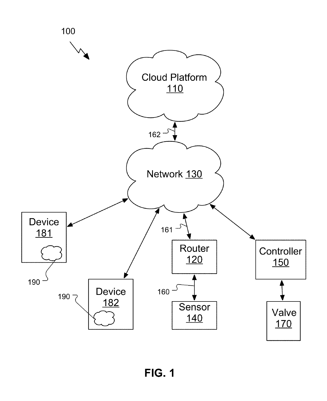
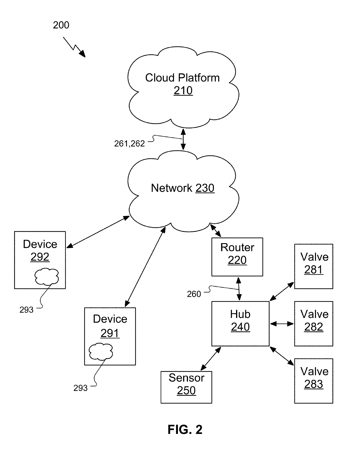
[0004]Systems and methods are described for obtaining environmental readings from within an electromagnetic-absorbing material. In some embodiments, a system may include an environmental sensor and a modulator coupled to the environmental sensor. The modulator may encode data from the sensor onto a carrier having a carrier frequency between about 9 kHz and about 1705 kHz. The system may also include a switch-mode amplifier powered from a self-contained power supply. The switch-mode amplifier may amplify the carrier which may then be transmitted via a multi-turn coil with a diameter of less than about 0.3 meter. The multi-turn coil may have a reactance at the carrier frequency that may form a part of a frequency-dependent load network coupled to the amplifier to minimize current and voltage during switching transients of the switch-mode amplifier.

Problems solved by technology

While various types of sensors are available for measuring environmental conditions within a material, communicating data from the sensors to outside the material can be challenging.
Using a wired connection can be successful, but wires are undesirable or impractical in many applications.
For example, in agriculture applications, wires are easily broken or damaged by rodent activity or tilling / harvesting operations.
In other applications, use of wired connections is undesirable due to the potential for vandalism, appearance, or other reasons.
While the use of wireless connections has been proposed to alleviate some of these problems, numerous challenges have prevented practical commercial application.
These challenges can include: inadequate communications range due to the attenuation of propagating electromagnetic waves (particularly in an electromagnetic-absorbing material), unreliable operation due to changes in electromagnetic characteristics of the material, large equipment / antenna sizes that are incompatible with easy installation / removal of buried sensors, and excessive power consumption incompatible with long-term or battery-powered operation.

Method used


Image

  • Sensing system and method for use in electromagnetic-absorbing material
  • Sensing system and method for use in electromagnetic-absorbing material
  • Sensing system and method for use in electromagnetic-absorbing material

Examples


example 1

[0174]A telemetry system for obtaining environmental readings from within an electromagnetic-absorbing material, the system comprising:

[0175]an environmental sensor having a sensor data output;

[0176]a modulator having a data input coupled to the sensor data output and a signal output, wherein the modulator encodes data received at the data input onto a carrier produced at the signal output, and wherein the carrier has a carrier frequency between about 9 kHz and about 1705 kHz;

[0177]a switch-mode amplifier coupled to the signal output and having an amplifier output;

[0178]a multi-turn coil coupled to the amplifier output, wherein the multi-turn coil has a diameter of less than about 0.3 meter, and wherein the multi-turn coil has a reactance at the carrier frequency that forms a part of a frequency-dependent load network coupled to the amplifier; and

[0179]a self-contained power source coupled to the switch-mode amplifier.

example 2

[0180]The telemetry system of Example 1, wherein the modulator comprises a digital processor configured to generate the carrier.

example 3

[0181]The telemetry system of Example 2, wherein the digital processor outputs the carrier as a substantially square wave, and wherein the amplifier converts the substantially square wave into a substantially sinusoidal wave.


PUM


Abstract

Systems and methods for obtaining telemetry environmental readings from within an electromagnetic-absorbing material are disclosed herein. The system may include a self-contained power source powering a switch-mode amplifier to drive a multi-turn coil to be driven with a low-frequency carrier.

Description

CROSS-REFERENCE TO RELATED APPLICATIONS[0001]This application is a continuation of U.S. patent application Ser. No. 16 / 009,192, filed Jun. 14, 2018; which is a continuation-in-part of U.S. patent application Ser. No. 15 / 614,945, filed Jun. 6, 2017, which issued as U.S. Pat. No. 10,191,184, issued Jan. 29, 2019, and which is a continuation-in-part of U.S. patent application Ser. No. 14 / 813,083, filed Jul. 29, 2015, which claims the benefit of, and priority to, U.S. Provisional Patent Application Ser. Nos. 62 / 030,559, filed Jul. 29, 2014, 62 / 030,566, filed Jul. 29, 2014, 62 / 030,568, filed Jul. 29, 2014, and 62 / 030,573, filed Jul. 29, 2014; and is a continuation-in-part of U.S. patent application Ser. No. 14 / 813,087, filed Jul. 29, 2015, which issued as U.S. Pat. No. 10,182,533, issued Jan. 22, 2019, and which claims the benefit of, and priority to, U.S. Provisional Patent Application Ser. Nos. 62 / 030,559, filed Jul. 29, 2014, 62 / 030,566, filed Jul. 29, 2014, 62 / 030,568, filed Jul. 29,...

Claims


Application Information

Patent Timeline
Patent Type & Authority Patents(United States)
IPC IPC(8): G01W1/02G05B19/042G08C17/02
CPCG05B19/0421G01W1/02G08C17/02H04Q9/00H04Q2209/40
Inventor CAMPBELL, JEFFREY E.
Owner GROGURU
Learn More